دوشنبه بیست و چهارم شهریور ۱۴۰۴ | 14:36 | حمید احمدیان -
Ammonia stress corrosion cracking (SCC), often abbreviated as NH3 SCC, is a hidden but potentially catastrophic threat that silently degrades equipment and piping across various industries, particularly those dealing with refrigerants and fertilizers. This article dives deep into the intricacies of NH3 SCC, focusing on its behaviour in two commonly affected materials: copper alloys and carbon steel.
It's important to recognize that although both materials are susceptible to NH3 SCC, the conditions that trigger cracking differ significantly. For copper alloys, NH3 SCC manifests as surface-initiated cracks caused by exposure to solutions containing ammonia or ammonium compounds (aqueous environments). In contrast, for carbon steel, NH3 SCC specifically targets non-post-weld heat treated (PWHT) welds and heat-affected zones (HAZs) when exposed to anhydrous ammonia (pure ammonia without water). This distinction highlights the crucial role of environmental conditions, material properties, and even processing history (like PWHT) in governing NH3 SCC susceptibility.
Copper Alloys: A Susceptible Target
Copper alloys, particularly those with a high zinc content (greater than 15%), are especially vulnerable to ammonia stress corrosion cracking (SCC) when they come into contact with ammonia-bearing services. While copper alloys boast excellent thermal conductivity and other desirable properties, their vulnerability to NH3 SCC makes them a poor choice for most applications directly involving ammonia. Here's a breakdown of the typical scenarios:
Refrigeration Systems: Copper alloys are often used in refrigeration systems due to their excellent thermal conductivity. However, if leaks develop, or trace amounts of ammonia from the refrigerant migrate, they can come into contact with these components. Even small quantities of ammonia dissolved in condensate water can initiate SCC, especially in alloys with high zinc content.
Chemical Processing Plants: In chemical processing plants, copper alloys might be present in piping, heat exchangers, or valves used for handling ammonia-based solutions or byproducts. These solutions can be concentrated or dilute, but the presence of both ammonia and water creates a perfect storm for SCC to occur, particularly if the operating temperatures are not tightly controlled.
Marine Applications: Copper alloys can find use in specific marine applications, such as seawater heat exchangers. While seawater itself doesn't pose a direct threat, if traces of ammonia (potentially from biological processes or pollution) contaminate the system and combine with even small amounts of moisture, SCC can initiate and compromise the integrity of these components.
Fertiliser Production: Anhydrous ammonia is a crucial component in fertilizer production. However, during storage, transportation, or processing, leaks can occur, exposing copper alloy components (like valves or piping) to ammonia vapor. While anhydrous ammonia itself might not trigger SCC in copper alloys, any incidental moisture condensing on the components can create a thin film of aqueous ammonia, initiating the detrimental cracking process.
This susceptibility of copper alloy to ammonia SCC arises from a complex interplay of several factors:
Temperature independence: Unlike many stress corrosion cracking (SCC) mechanisms, ammonia SCC in copper alloys shows minimal influence from temperature variations. This difference arises because the process of crack growth doesn't rely on the increased movement of atoms due to heat, which is a defining characteristic of thermally activated processes. Instead, the driving force behind crack propagation here is the ongoing chemical interaction between ammonia and copper alloy. This interaction weakens the metallic bonds within the copper lattice, and the extent of this weakening is independent of temperature. In simpler terms, the presence of ammonia creates a constant vulnerability in the copper alloy, and the rate of crack growth is primarily determined by this chemical effect rather than by the thermal energy of the system. We will explore deeper into the specifics of the chemical interactions between ammonia, copper, and zinc in the next section.
Zinc's detrimental role: Zinc's presence in copper alloys significantly increases SCC susceptibility. At the atomic level, ammonia molecules (NH₃) can readily chemisorb (form strong chemical bonds) onto the copper surface. However, when zinc atoms are present, they disrupt the copper lattice, creating preferential sites for ammonia adsorption. This localized enrichment of ammonia weakens the metallic bonds at these sites, facilitating crack initiation and propagation.
This vulnerability stems from the interaction of several chemical and metallurgical factors:
Strong Chemical Bonding of Ammonia to Copper: Ammonia molecules (NH₃) readily form strong chemical bonds with the copper (Cu) atoms on the surface of the alloy. This attraction arises from the electron configuration of both species. Copper atoms possess partially filled d-orbitals, which can readily accept electron density from the lone electron pairs on the nitrogen atom (N) in ammonia. This electron donation creates a force of attraction between the NH₃ molecule and the Cu atom, resulting in a strong chemical bond.
Disruption of the Copper Lattice by Zinc: The introduction of zinc (Zn) atoms, smaller than copper atoms, into the copper lattice disrupts its ordered atomic arrangement. This size difference causes zinc atoms to fit imperfectly, creating localised areas of strain and distortion around them. These distorted regions become preferential sites for ammonia chemisorption because the disrupted bonding environment offers a more favourable interaction (both chemically and metallurgically). Chemically, the strained copper atoms possess altered electron distribution, making them more attractive electron acceptors for ammonia's lone electron pairs. Metallurgically, the distortions create more open spaces around the zinc atoms, allowing ammonia molecules to pack more efficiently and chemisorb more readily.
Localised Enrichment and Bond Weakening: The preferential adsorption of ammonia at these zinc-induced lattice distortions leads to a localised enrichment of ammonia molecules on the copper alloy surface. This enrichment has a detrimental effect on the strength of the metallic bonds between copper atoms. Ammonia acts as a Lewis base, donating electron density to the Cu atoms. This disrupts the balanced electron sharing between neighbouring copper atoms in the lattice, weakening the metallic bonds (copper-copper bonds) in the vicinity of the chemisorbed ammonia. This localised weakening of metallic bonds creates a critical region susceptible to crack initiation and propagation under applied stress.
The 15% threshold for zinc content is important because at concentrations below 15%, the number of zinc atoms disrupting the lattice is relatively low. This limits the number of preferential sites for ammonia adsorption and weakens the overall effect on copper-copper bond strength. However, as the zinc content increases above 15%, the number of distorted regions and preferential sites grows significantly. This leads to a more pronounced enrichment of ammonia, consequently weakening a greater number of copper-copper bonds and significantly increasing the susceptibility of the alloy to ammonia SCC.
Aqueous solution requirement: Ammonia SCC in copper alloys can be detrimental in both the liquid and vapor phases of ammonia. However, Ammonia SCC in copper alloys thrives in aqueous environments, where liquid ammonia coexists with dissolved water. Water's presence isn't just incidental; it plays a crucial role in the overall process. Here's the breakdown:
· Partial Dissociation of Ammonia: Water facilitates the dissociation of a portion of ammonia molecules (NH₃) into ammonium (NH₄⁺) and hydroxide (OH⁻) ions:
However, it's important to remember that this is an equilibrium reaction. While some ammonia converts to ions, a significant amount remains as free NH₃ molecules in the solution.
· Enhanced Ammonia Chemisorption: The primary driver of ammonia SCC in copper alloys remains the direct chemisorption of free ammonia molecules (NH₃) onto the copper surface. As explained previously, copper's partially filled d-orbitals readily accept electron density from the lone electron pairs on the nitrogen atom in ammonia, forming a strong chemical bond. This chemisorption weakens the existing copper-zinc bonds within the alloy, making the material more susceptible to crack propagation under stress.
· Subtle Influence of Hydroxide on Chemisorption (Possible): While not the main culprit, the presence of hydroxide ions (OH⁻) might play a secondary role. These ions could interact with the copper-zinc lattice, subtly altering the electronic environment around copper atoms. This potential change could make the copper atoms slightly more receptive to chemisorption of the remaining free ammonia molecules in the solution. However, the exact mechanisms of this influence require further exploration. The presence of hydroxide ions can also indirectly weaken the existing copper-zinc bonds within the alloy. This weakening can occur through various mechanisms, such as the formation of copper hydroxide complexes at the surface or the disruption of interatomic forces between copper and zinc.
· Enhanced Mass Transport by the Liquid Phase: The presence of a liquid phase (aqueous ammonia) offers a significant advantage for the SCC process compared to a purely gaseous environment. In a liquid, both ammonia molecules (NH₃) and hydroxide ions (OH⁻) can diffuse much more readily towards the metal surface. This enhanced mobility accelerates the overall SCC process by facilitating faster delivery of the detrimental species to the copper-zinc lattice.
· The Importance of the Liquid Phase: Beyond the chemical influence, the presence of a liquid phase (aqueous ammonia) is crucial from a metallurgical perspective. Compared to a purely gaseous environment, the liquid medium allows for significantly easier diffusion of both ammonia molecules and hydroxide ions towards the metal surface. This enhanced mobility accelerates the overall SCC process by facilitating faster delivery of the detrimental species to the copper-zinc lattice.
In essence, while water consumes some ammonia through dissociation, a significant amount of free ammonia molecules (NH₃) remains in the solution. These free ammonia molecules are the primary culprits in chemisorbing onto the copper surface and weakening the copper-zinc bonds. The presence of hydroxide ions might play a minor role in influencing chemisorption, but the key factor remains the direct interaction between free ammonia and the copper alloy. The liquid phase further accelerates the process by allowing for faster transport of these detrimental species to the metal surface. We will delve deeper into the specifics of these interactions in later sections.
pH dependence: In environments with a high pH (above 8), the dissociation of water leads to a greater concentration of hydroxide ions (OH⁻). As mentioned above, these ions might have a subtle influence on ammonia chemisorption, potentially making the copper surface slightly more receptive to the remaining free ammonia molecules. The exact mechanisms are still being explored, but the altered electronic environment around copper atoms due to hydroxide interaction is a possibility. Additionally, highly alkaline conditions can promote the formation of specific copper hydroxide complexes that could contribute to the weakening of copper-zinc bonds. It's important to note, however, that the influence of pH on ammonia SCC is considered secondary compared to the dominant effects of free ammonia and zinc.
The susceptibility of copper alloys to ammonia SCC is primarily governed by the presence of free ammonia molecules and the weakening effect of zinc on the copper lattice. The influence of pH, while a factor, is less critical. Nevertheless, highly alkaline environments (pH > 8) can potentially exacerbate the SCC process through the mechanisms described above. We will explore these interactions in more detail in later sections.
The critical role of oxygen: Even trace amounts of oxygen (O₂) can significantly worsen ammonia SCC in copper alloys. However, oxygen's influence is a double-edged sword. Initially, it reacts with the copper surface to form a thin layer of copper oxide (Cu₂O) according to the following reaction:
4 Cu (s) + O₂ (g) → 2 Cu₂O (s)
This oxide layer might appear beneficial, acting as a protective barrier against further corrosion. However, in the presence of ammonia, this seemingly protective layer becomes detrimental due to a combination of metallurgical and chemical factors.
Firstly, the formation of copper oxide introduces internal stresses within the layer and the underlying copper matrix. This stress arises from the differing thermal expansion coefficients of the metal and the oxide. This inherent brittleness makes the oxide layer more susceptible to cracking under stress, potentially acting as initiation sites for further crack propagation.
Secondly, ammonia can interact with the copper oxide layer, further weakening it:
Dissolution: Ammonia might partially dissolve the Cu₂O, leading to a thinner and more vulnerable layer.
Brittle Complex Formation: Ammonia might react with the oxide to form specific copper-ammonia complexes within the Cu₂O layer. These complexes could be brittle and contribute to crack initiation and propagation.
The combined effect of these factors is a weakened and brittle oxide layer that readily cracks under stress. These cracks then act as initiation sites for further propagation into the underlying copper alloy, significantly accelerating the SCC process in the presence of ammonia.
while the Cu₂O layer and its interaction with ammonia play a significant role, it's crucial to remember that trace oxygen acts as a catalyst, not the sole culprit. The primary driver of ammonia SCC remains the direct chemisorption of free ammonia molecules onto the copper surface, weakening the copper-zinc bonds and facilitating crack initiation and propagation. We will delve deeper into the specifics of these interactions in later sections.
Stress: The stress required for ammonia SCC in copper alloys can be either residual stress (introduced during manufacturing) or applied stress (due to pressure or external loads). Even seemingly low stress levels can be detrimental in the presence of ammonia and the aforementioned factors.
Carbon Steel: A Different Battleground
In contrast, ammonia SCC in carbon steel is primarily observed in the liquid phase of ammonia, not the vapour phase. The liquid phase provides a more efficient medium for ammonia molecules to dissolve into the steel and interact with the iron atoms. The exact mechanism for SCC in carbon steel exposed to liquid ammonia is still being actively researched. It's believed to be a more complex interaction than the one observed in copper alloys.
Potential Mechanisms: Some potential mechanisms for SCC in carbon steel include:
· Direct Interaction with Iron: Ammonia molecules might directly interact with iron (Fe) atoms in the steel lattice. This interaction could weaken the interatomic bonds between iron atoms, making the material more susceptible to cracking under stress. The specifics of this interaction are still being explored.
· Environmental Factors: The presence of additional environmental factors, such as contaminants (e.g., sulfides) or specific pressures, might play a role in influencing the SCC process. These factors could potentially influence the ammonia's interaction with the steel or promote the formation of cracks.
Why Not Hydrogen Embrittlement?
In classic hydrogen embrittlement, water or other sources introduce hydrogen (H) atoms into the steel lattice. These hydrogen atoms can diffuse and combine to form hydrogen molecules (H₂) within the steel. The presence of H₂ gas puts the steel under internal pressure and weakens the interatomic bonds, making it more susceptible to cracking.
However, in ammonia SCC of carbon steel, the primary reaction product isn't hydrogen. While some complex secondary reactions might involve the formation of small amounts of hydrogen, it's not the main driver of the SCC process. The focus here is on the direct interaction between ammonia and the steel lattice.
Temperature and its influence: Generally, the risk of ammonia SCC in carbon steel increases significantly at temperatures above -35°C. This observation aligns with the concept of thermally activated processes. At higher temperatures, ammonia molecules (NH₃) have greater kinetic energy, allowing them to move and interact with the steel surface more efficiently. This facilitates the adsorption of ammonia molecules onto the steel and potentially weakens the interatomic bonds within the lattice. Higher temperatures might also enhance the mobility of other species within the steel, such as vacancies or dislocations in the crystal lattice. These mobile species could potentially interact with ammonia and contribute to crack initiation and propagation.
While the exact link needs further investigation, the limited solubility of oxygen in water at lower temperatures (below -35°C) might be a contributing factor. Here's why:
Trace amounts of oxygen can influence ammonia SCC in some cases. However, in carbon steel's case, the exact mechanism isn't fully understood. Colder temperatures generally lead to lower dissolved oxygen levels in water. This could potentially influence the overall SCC process in ways that are still being explored. It's important to note that this is a hypothesis, and other factors might play a more significant role.
The -35°C Threshold: Not a Rigid Cut-off
The -35°C threshold shouldn't be considered a rigid cut-off point. The susceptibility to SCC can vary depending on several factors, including:
Specific Steel Composition: The presence of additional elements in the steel alloy can influence its susceptibility to SCC. Some alloying elements might improve resistance, while others might make it more susceptible.
Presence of Contaminants: The presence of contaminants like sulfides in the steel or the environment can play a role in influencing the SCC process.
Stress Levels: The applied stress on the steel component significantly affects its susceptibility to cracking. Higher stress levels can exacerbate SCC even at lower temperatures.
Oxygen's necessity: The influence of oxygen on ammonia stress corrosion cracking (NH3 SCC) differs between copper alloys and carbon steel. In copper alloys, trace amounts of oxygen significantly exacerbate SCC by forming a weak oxide layer that becomes susceptible to ammonia attack. For carbon steel, the impact of oxygen is less clear-cut. While some operators in the industries recommended a threshold effect, where oxygen levels above 0.5 ppm might promote SCC, the presence of water can counteract this effect. Overall, the role of oxygen in carbon steel SCC appears to be secondary compared to its significant influence on copper alloys. However, research on the exact mechanisms in carbon steel is ongoing. Here are two potential scenarios:
Indirect Effect on Steel Surface: Trace amounts of oxygen could potentially alter the surface chemistry of the steel, making it slightly more susceptible to ammonia attack. The exact mechanisms are still under investigation.
Oxide Formation and Subsequent Breakdown (Less Likely): In some theories, oxygen might react with steel to form a thin layer of iron oxide (Fe₂O₃). However, the current understanding suggests this oxide layer is unlikely to be a significant factor. Ammonia is believed to be capable of directly interacting with the steel surface and weakening the interatomic bonds regardless of the presence of an oxide layer.
The Protective Role of Water: A Chemical and Metallurgical Perspective
Interestingly, the presence of water (at or above 0.2 wt%) can significantly inhibit ammonia SCC in carbon steel. This phenomenon can be explained through a combination of chemical competition and the formation of a more protective surface layer.
Chemical Competition for Adsorption Sites:
At the microscopic level, ammonia (NH₃) molecules and water molecules (H₂O) compete for adsorption sites on the steel surface. This competition arises due to the similar polarity of both molecules. Ammonia has a lone electron pair on the nitrogen atom, making it a Lewis base capable of donating electrons to form bonds with the iron atoms on the steel surface. However, water also has a polar covalent bond with a partially positive hydrogen and an oxygen end, allowing it to interact with the steel surface as well.
Chemical Reactions:
When the water concentration is sufficiently high (above 0.2 wt%), it preferentially occupies the adsorption sites, hindering the adsorption of ammonia molecules. This reduces the overall surface coverage of ammonia on the steel, thereby limiting its ability to directly weaken the iron-iron bonds within the steel lattice.
Metallurgical Aspect: The Role of the Oxide Layer (if present):
While the oxide layer's significance in ammonia SCC is debated, its presence can still play a role in some scenarios. Here's the potential interplay:
Iron Oxide and Water Reaction: Water can react with the existing iron oxide layer (primarily Fe₂O₃) on the steel surface to form a new layer of iron hydroxide (Fe(OH)₃). This reaction can be represented as:
Fe₂O₃ (s) + 3H₂O (l) → 2Fe(OH)₃ (s)
Enhanced Protection by Hydroxide Layer: The iron hydroxide layer is considered more stable and protective compared to the iron oxide layer. It might present a physical barrier that hinders the diffusion of ammonia molecules towards the underlying steel matrix. Additionally, the hydroxide layer might have a weaker interaction with ammonia compared to the oxide layer, further reducing the detrimental effects of ammonia adsorption.
Keeping Ammonia SCC at Bay
Ammonia SCC poses a serious threat to equipment in various industries. Understanding how ammonia interacts with copper alloys and carbon steel is key to preventing it. By choosing the right materials, controlling factors like temperature and water content, and using techniques like PWHT in carbon steel, engineers can significantly reduce the risk of ammonia SCC and ensure safer industrial operations.
شش سیگما (Six Sigma) اصطلاحی است که برای تعریف تکنیکهای مختلف و ابزارهای مدیریتی طراحی شده است تا فرآیندهای تجاری به شکل کارآمدتر و موثرتری انجام شوند. این روش در دهه 1980 میلادی توسط یکی از دانشمندان شرکت موتورولا توسعه پیدا کرد. شش سیگما مجموعهای از روشها و ابزارها برای بهبود فرآیند کسبوکار و مدیریت کیفیت است. این اصول به شما کمک میکند تا آنچه در سازمان انجام میدهید، اندازهگیری کنید، عیوب و علت بروز مشکلات را شناسایی کرده و در جهت افزایش دقت و بهبود فرآیندها تصمیمگیری کنید. با بهبود کارآیی و کاهش عیوب، کیفیت و شرایط تحویل محصول بهبود مییابد و تاثیر زیادی روی اشتیاق و اعتماد کارکنان خواهد داشت که روی بهبود عملکرد کلی شرکت و رضایت مشتریان تاثیرگذار است.
بسیاری از مشاوران معتقدند که هیچ صنعتی نیست که نتواند از روش شش سیگما بهرهمند شود. اصول شش سیگما در هر فرآیند و صنعتی قابل اجرا است و سیستم مدیریتی را در جهت شناسایی خطاها و افزایش سودآوری کسبوکار راهنمایی میکند. فرآیند شش سیگما با کمک آمار و تجزیهوتحلیل دادهها به کاهش خطاها کمک میکند تا تواناییهای سازمان برای مدیریت کسبوکار افزایش پیدا کند.
پنج اصل کلیدی شش سیگما
مفهوم شش سیگما یک هدف ساده دارد که عبارت است از ارائه کالا و خدمات عالی برای کسب رضایت مشتریان که به وسیله ایجاد تغییرات در کسبوکار فراهم میشود. این رویکرد دارای پنج اصل کلیدی است که در این بخش آنها را شرح خواهیم داد:
1.تمرکز بر مشتری
بسیاری از کسبوکارها بر این باور هستند که مشتری پادشاه است و هدف اصلی هر کسبوکاری، تامین حداکثر نیازهای مشتریان است. برای این کار، یک کسبوکار باید شناخت کاملی از مشتریان و نیازهای آنها داشته باشد و درک درستی از عوامل فروش و وفاداری آنها بهدست بیاورد. رسیدن به این هدف مستلزم ایجاد استانداردهای کیفیت با توجه به تقاضای مشتریان است.
2.ارزیابی زنجیره ارزش و شناسایی مشکل
ابتدا باید مراحل یک فرآیند ترسیم شود تا بتوان بخشهای مشکلساز را شناسایی کرد و به جمعآوری داده در این زمینه پرداخت. در این اصل، کسبوکار باید اهداف مشخصی برای جمعآوری داده داشته باشد، یعنی تعریف درستی از داده موردنیاز را داشته باشد، علت جمعآوری داده را شناسایی کند و در عین حال دقت اندازهگیری بالایی داشته باشد تا بتواند یک سیستم جمعآوری داده استاندارد تعریف کند. پس از جمعآوری دادهها، مشکلات قابل شناسایی خواهند بود و بهراحتی میتوان علت اصلی را پیدا کرد.
3.از بین بردن عیوب و موارد اضافی
پس از شناسایی مشکل، باید فرآیند رفع عیوب آغاز و اصلاحات مناسب ایجاد شود. در این مسیر بهتر است هرگونه فعالیتی که به ارزش مشتری اضافه نمیکند حذف شود. ابزارهای مختلفی برای کشف نقاط پرت و اضافی وجود دارد که حذف آنها، گلوگاههای یک فرآیند را از بین میبرد.
4.مشارکت دادن افراد تیم
در شش سیگما باید یک فرآیند ساختاریافته ایجاد شود که در آن تمام افراد تیم با یکدیگر همکاری داشته باشند و برای حل مسائل پیچیده مشارکت داشته باشند. در ساختار تیم، باید افراد متخصص با مهارتهای مختلف برای کاهش خطرات شکست پروژه یا اطمینان از عملکرد بهینه فرآیندها همکاری داشته باشند.
5.سیستم انعطافپذیر و پاسخگو
زمانیکه یک سیستم ناکارآمد یا معیوب حذف شود، رویکرد کارکنان و روشهای کاری نیاز به تغییر خواهد داشت. یک محیط کاری منعطف و پاسخگو به تغییرات منجر به اجرای کارآمد پروژهها میشود. تمام بخشهای درگیر با تحول، باید توانایی سازگاری با تغییرات را داشته باشند. در چنین شرایطی، شرکتهایی که به صورت دورهای دادهها را بررسی میکنند و تغییرات مناسبی در فرآیندهای خود ایجاد میکنند، نوعی مزیت رقابتی بهشمار میرود.
روش شناسی شش سیگما
شش سیگما در محیطهای تجاری مختلف، از دو روش کاربردی برای حل مشکلات استفاده میکند که در این بخش به معرفی این دو روش میپردازیم:
DMAIC یک رویکرد دادهمحور است که برای بهینهسازی و بهبود فرآیندهای تجاری مورد استفاده قرار میگیرد. این روش، یک راه حل موثر برای مدیریت تغییر است که مراحل آن مطابق فهرست زیر است. در این رویکرد، هر مرحله شامل ابزار و وظایفی است که برای یافتن راه حل نهایی به کسبوکار کمک میکنند.
تعریف (Define): مشکل و اهداف پروژه را تعریف کنید.
اندازهگیری (Measure): جنبههای مختلف فرآیند موجود را با جزییات اندازهگیری کنید.
تجزیهوتحلیل (Analyze): دادهها را برای کشف نقص اصلی در فرآیند، تجزیهوتحلیل کنید.
بهبود (Improve): از راهحل تعیینشده برای بهبود فرآیند کمک بگیرید.
کنترل (Control): در پایان باید نحوه اجرای فرآیند را در آینده کنترل کنید.
DMADV بر توسعه یک فرآیند، محصول یا خدمت جدید تمرکز دارد. این روش زمانی مورد استفاده قرار میگیرد که فرآیندهای موجود، حتی پس از بهبود، پاسخگوی نیازهای مشتریان نباشند و توسعه روشهای جدید راه حل بعدی باشد. DMADV شامل پنج مرحله زیر است:
تعریف (Define): هدف پروژه، محصول و یا خدمت را مشخص کنید.
اندازهگیری (Measure): اجزای حیاتی یک فرآیند و قابلیتهای محصول را اندازهگیری کنید.
تجزیهوتحلیل (Analyze): در این مرحله باید با تجزیهوتحلیل دادهها و توسعه جایگزینهای طراحی، بهترین طرح را انتخاب کنید.
طراحی (Design): بهترین جایگزین انتخابشده را طراحی کرده و نمونه اولیه آن را تست کنید.
بررسی (Verify): میزان اثربخشی فرآیند را با کمک شبیهسازی و برنامههای آزمایشی مختلف بررسی کنید.
گواهینامه شش سیگما
اجرای اصول شش سیگما متکی بر تیمی متخصص و آموزشدیده است که با بهکارگیری افراد مناسب، موفقیت سازمان را تضمین میکند. برای دستیابی به این هدف، افراد تیم باید آموزش شش سیگما را دیده باشند. سازمانهای مختلفی قابلیت ارائه گواهینامه شش سیگما را دارند که شرایط هر کدام با توجه به درجه کمربند و موسسه متفاوت است. برای اخذ این گواهینامه باید در دوره آموزشی و امتحان عملی شرکت کنید و مدرک خود را بر اساس استانداردهای روز تمدید کنید. در این بخش به معرفی سطوح مختلف شش سیگما میپردازیم که با الهام از هنرهای رزمی، با عنوان (کمربند) شناخته میشود.
کمربند سفید: هر تازهواردی در این دسته قرار میگیرد و افراد با تیمها روی حل مسئله و پروژه کار میکنند.
کمربند زرد: افرادی که در این سطح هستند معمولا به عنوان عضو تیم پروژه هستند و دانش پایهای از شش سیگما دارند. در این مرحله افراد میتوانند با تکمیل کارهایی مانند ایجاد نقشه فرآیند و… درک بهتری از این استراتژی داشته باشند.
کمربند سبز: در این سطح، افراد با هدایت کمربندهای سیاه، توصیههای شش سیگما را به عنوان بخشی از وظایف عادی خود اجرا میکنند. در این مرحله فرد باید درک درستی از ابزارها و روشهای حل مسئله داشته باشد و تجربه عملی در پروژههای دیگر داشته باشد.
کمربند سیاه: این افراد تحت نظارت سطح کمربند مشکی حرفهای هستند و مسئولیت اجرای متدولوژی شش سیگما را برای پروژههای خاص به عهده دارند. تمرکز این دسته روی تجزیهوتحلیل آماری و اجرای صحیح روش شش سیگما است.
کمربند مشکی حرفهای: افراد کمربند مشکی حرفهای توسط یک سطح بالاتر از خود انتخاب میشوند. این سطح معمولا وظیفه آموزش سطوح کمربند سبز و سیاه را به عهده دارد و پروژههای شش سیگما را برای سازمان شناسایی میکند.
قهرمانان: قهرمانان توسط بالاترین سطح، یعنی رهبر اجرایی انتخاب میشوند. این افراد باید از همکاری تمام بخشهای سازمان اطمینان حاصل کنند تا شش سیگما به خوبی پیادهسازی شود. علاوهبر این، راهنمایی سطح کمربند مشکی حرفهای نیز به عهده این سطح است.
رهبر اجرایی:مدیر عامل و سایر سرپرستان اجرایی با داشتن چشمانداز صحیحی از پیادهسازی شش سیگما، وظیفه مدیریت و پشتیبانی تیم را به عهده دارند.
جمعبندی
در دنیای رقابتی امروز، برای کسب موفقیت در کسبوکارها همواره باید به دنبال راههایی برای بهبود فرآیندها باشیم. یکی از این راهها، اصول شش سیگما است که با شناسایی مشکلات فرآیند و حل مسائل به بهبود فرآیند کمک میکند و بستر مناسبی برای تغییر و تحول در فرآیند سازمان ایجاد میکند. در این مطلب از كنترل كيفيت با مفهوم شش سیگما و اصول آن آشنا شدید و شناخت بهتری برای مدیریت استراتژیک در سازمان خواهید داشت
اصول بازرسی مخازن تحت فشار به زبان ساده مخزن تحت فشار چیست ؟! مخزن تحت فشار را اینگونه تعریف میکنند : به محفظه که برای نگهداری مایعات یا گازها در فشاری بیشتر از فشار بیرون ساخته میشود ، مخزن تحت فشار و به انگلیسی Pressure Vessel گفته میشود . مخازن تحت فشار در همه جا وجود دازند از خانه گرفته تا پالایشگاه ها آنها کاربرد دارند .
اصول بازرسی مخازن تحت فشار امروزه مخازن تحت فشار در صنعت کاربرد بسیار زیادی دارند ، بطوریکه در صنایع نفت و گاز ، پتروشیمی ، پالایشگاه ها و نیروگاه ها این مخازن وظیفه حیاتی را برعهده دارند . مخازن تحت فشار انواع مختلـــفی دارند و از نمونـــه های ساده که برای نگهداری هوای فشرده (منبع کمپرسور) استفاده میشوند تا مدل های بسیار پیشرفته تر که در پالایشگاه ها مورد استفاده قرار میگیرند ، کاربرد دارد .
مخازن تحت فشار به گونه های متفاوتی طراحی میشوند و این طراحی بر اساس کاربرد آنها انجام میشود . عموماً ظاهر کلی مخازن تحت فشار شبیه به هم است و دارای بدنه ایی استوانهایی یا کروی شکل هستند که بعلت کاهش تمرکز تنش به این شکل ساخته میشوند
مخازن تحت فشار همانقدر که میتوانند مفید باشند به همان اندازه میتوانند خطرناک باشند چرا که این مخازن حاوی مقدار زیادی انرژی ذخیره شده هستند و اختلاف فشار داخل و بیرون مخزن تحت فشار پتاسیل ایجاد اتفاقات ناگوار را دارد و در صورت تخریب مخزن این انرژی بصورت ناگهانی آزاد شود که خسارات جانی و مالی زیادی را بهمراه خواهد داشت ، بد نیست که اشاره کنم معمولاً لاستیک ماشین باد شده فشاری در حدود ۳۰ تا ۳۵ psi دارد که تقریباً فشاری معادل برابر با ۲.۳ برابر فشار هوا است میشود ، و احتمالاً میدانید اگر لاستیک ماشین ناگهانی بترکد چه پیامدهای را در بر خواهد داشت حال تصور کنید مخازت تحت فشار کم فشار (low-pressure) فشاری بالغ بر ۳۰۰psi دارد . پس احتیاط های لازم برای پیشگیری از خرابی ناگهانی مخزن حیاتی است .
از این رو مهمترین هدف در بازرسی مخازن تحت فشار یا FFP مخازن که مخفف کلمـــه انگلیسی Fitness For Purpose میباشد این است که از سلامت مخازن تحت فشار ، آگاهی و اطمینان کامل داشتــه باشیم .
عوامل متعددی روی عمر مخزن تاثیــرگذار هستند ، تعدادی از عوامل مانند : خستــگی ، خزش ، خوردگی و شرایط محیطی و …. هستند . اما چگونه میتوان سلامت آنهــــا را تضمین کرد ؟!! تقریباً از اوایل قرن ۲۰ ام که صنعت رشد چشمگیـــری را شاهد بود مخازن تحت فشار کاربرد زیادی در صنعت پیدا کردند و از طرف دیگر در این سالها شاهد حوداث ناگوار زیادی در مورد ترکیدن این مخازن بودیم اما خوشبختانه دانش طراحی و ساخت مخازن تحت فشار به مرور توسعه یافت و امروزه ما این دانش را در یک چهارچوب مدون به عنوان استاندارهای طراحی مخازن تحت فشار داریم ، که احتمال به وجود آمدن حادثه را تا حد امکان کاهش داده است .
انواع مخازن تحت فشار مخازن تحت فشار در سه مدل کلی بشرح زیر طراحی و ساخته میشوند.
۱) مخزن ذخیره مخزن ذخیره یا Storage Tank متداول ترین نوع مخزن تحت فشار است که در انواع و شکل های مختلف تولید میشود و برای دخیره مایعات و گازها تحت فشار ساخته میشوند . این مخازن معمولاً از جنس فولاد کم کربن ساخته میشوند و داخل آنها توسط فلز دیگری پوشش داده میشود اصطلاحا کوتینگ (Coating) میشود .
۲) مبدل گرمایی مخازن تحت فشار از نوع مبدل گرمایی یا Heat Exchangers بعد از مخازن تحت فشار نگهداری (Storage Tank) پر کاربردترین نوع مخزن میباشند . این نوع مخازن در پروسه های تولیدی که نیاز به سرد و گرم کردن به منظور رسیدن به یک محصول دیگر وجوذ دارد استفاده میشود ، این نوع از مخازن بیشتر در تولیدات مواد شیمیایی کاربرد دارند .
۳) مخازن پروسهایی مخازن پروسهایی یا به انگلیسی Process Vessels نام پیشنهادی برای مخازن تحت فشاری هستند که یک عملیات تولیدی را در داخل محفظهایی کنترل شده را به غایت می رسانند . این فرآیند میتواند شامل ترکیب کردن ، جداسازی و همگن سازی مواد باشد .
بازرسی مخازن تحت فشار چیست و چه زمانی لازم است؟ همانطور که قبلاً اشاره شد بازرسی مخازن تحت فشار به منظور اطمینان از سلامت آن انجام میشود ، اما اینکه چه زمانی باید بازرسی از آنها انجام بشود ، دو حالت وجود دارد ۱) بازرسی مخزنی که به تازگی ساخته شده است و باید از سلامت آن مطمئن شویم ۲) مخزنی که قبلاً ساخته شده است و الان زمان بازرسی دورهایی آن فرارسیده است .
بازرسی مخازن تست فشار با روش تست غیر مخرب یا NDT که مخفف کلمه انگلیسی Non Destructive Testing است انجام میشود که در ادامه این مقاله آنها را بررسی خواهیم کرد و اگر بصورت تخصصی تر میخواهید با آنها آشنا بشوید مقاله { سیر تا پیاز تست غیر مخرب NDT } را مطالعه فرمایید .
همانطور که در بالاتر اشاره شد با آغاز رشد صنعت نیاز به ساخت مخازن تحت فشار بیشتر شد و از رو در این سالها حوادث زیادی به علت ترکیدن این مخازن به وجود آمده است . انجمن مهندسین مکانیک آمریکا یا ASME با گردآوری این اطلاعات و دسته بندی آنها و علت یابی حوادث گذشته ، یک چهارچوب برای طراحی و ساخت مخازن تحت فشار را ایجاد کرده است ، که امروزه ما آن را بعنوان استاندارد میشناسیم .
مجموعه استانداردهای انجمن مهندسین مکانیک آمریکا ، علاوه کشور ایالت متحده امریکا در سایر کشور ها نیز مورد استفاده قرار میگیرند . دو استاندارد اساسی در طراحی و ساخت مخازن تحت فشار وجود دارد که هر سازنده ایی باید از آن مطلع باشد .
۱) ASME Section VIII : این استاندارد برای طراحی مخازن تحت فشاری که هم در معرض گرمای مستقیم هستند و هم مخازنی که در معرض گرمای مستقیم نیستند ، کاربرد دارد و اطلاعات لازم برای بازرسی این مخازن در این استاندارد وجود دارد .
۲) API 510 : این استاندارد برای بازرسی مخازن تحت فشار از سوی موسسه API آمریکا تدوین شده است . در این استاندارد علاوه بر نحوه بازرسی ، اطلاعاتی در مورد تعمیر آن وجود دارد .
علاوه بر این دو استاندارد فوق ، در صنایع خاص و موسسات صنایع های- تک (High-Tech) برای طراحی و ساخت مخازن استاندارد هایی تدوین کرده اند ، برای مثال ناسا (NASA) برای مخازن ذخیره سوخت با توجه به شرایط کاری آنها در جو و خارج از جو ، استاندارد هایی ویژه خودش تدوین کرده است .
ساخت مخازن تحت فشار باید طبق اصول و راهنمایی استانداردها پیش برود ، اما این موضوع به تنهایی کافی نمیباشد ، بلکه باید تائید شود که استفاده از این مخزن امنیت کافی را دارد ، و در اینجا است که نقش بازرسی مخازن تحت فشار آشکار میگردد . روش ها و تست های متعددی برای این موضوع وجود دارد که اطمینان از امنیت مخزن زمانی حاصل میشود که تمامی این تست ها را پاس کند .
بازرس مربوطه علاوه بر انجام دو تست فوق یعنی تست اولیه و تست دوره ایی باید ، تست میان دوره ایی یا تست اتفاقی از مخزن بگیرد که احتمال به وجود آمدن حادثه را تا حد امکان کاهش بدهد .
روش های بازرسی مخازن تحت فشار مخازن تحت فشار باید بتوانند فشار داخلی خود را حفظ کنند ، وجود هیچگونه نشتی در این مخازن قابل اغماض نیست . این تست ها برای اطمینان از نداشتن سوراخ نشتی هوا (punctures) ، ترک و اتصلات ضعیف انجام میشود که وجود این عیوب سلامت مخزن را تهدید میکنند .
دو روش هیدرواستاتیک و روش پنوماتیک ، روشهای ابتدایی برای تست مخازن هستند اما این دو روش بعلت ریسک بالایی که داشتند امروزه کمتر از آنها استفاده میشوند . اساس این دو روش تقریباً مشابه یکدیگر است ، در روش هیدرواستاتیک معمولا از آب استفاده میشود و روش پنوماتیک از گازی غیر سمی و غیر قابل اشتعال مانند هوا یا نیتروژن استفاده میشود .
در این دو روش سیال را به یک آشکارساز یا فلورسنت ، آلوده میکند و مخزن را تحت فشار ۱.۵ برابر فشار کاری قرار میدهند و در این شرایط مخزن نباید هیچ گونه نشتی داشته باشد . این روش بعلت ریسک بالایی که دارد امروزه تقریباً کنار گذاشته شده است و روش های تست غیر مخرب بسیار متداول تر هستند . در ادامه ۵ روش متداول در بازرسی مخازن تحت فشار به روش غیر مخرب را بررسی خواهیم کرد .
۱) روش بازرسی چشمی روش بازرسی چشمی یا VT که مخفف کلمه انگلیسی Visual Testing است ، یک ارزیابی خوب از وضعیت مخزن میباشد ، برای انجام این تست باید سطح مخزن کاملاً تمیز شود و تمام قسمت های آن توسط بازرس ، مانند خطوط جوش ، اطراف زائده ها و … مشاهده گردد .
روش بازرسی چشمی به تنهایی کافی نمیباشد چون در این روش بازرسی فقط عیوبی که روی سطح وجود دارند ، قابل تشخیص است .
۲) روش بازرسی مایع نافذ روش بازرسی مایع نافذ یا PT که مخفف کلمه انگلیسی Penetrant Testing است در این روش ابتدا سطح محل تست کاملاً تمیز میشود سپس محل مورد نظر آغشته به مایع نافذ میشود و مدتی را بازرس باید منتظر بمانند تا اصطلاحاً مایع نافذ ترک ها و عیوب سطحی را خیس کند و بعد از آن سطح از وجود مایع نافذ پاکسازی میشود و مایع آشکار ساز روی سطح اسپری میشود ، و این موجب میشود مایعی که سابقاً در داخل عیوب نفوذ کرده خود را به سطح برساند و عیوب را آشکار کند .
۳) روش بازرسی مغناطیس روش بازرسی مغناطیس یا MT که مخفف کلمه انگلیسی Magnetic Testing است ، در این روش قطعه مورد تست مغناطیسی میشود و بازرس مربوطه مقداری ذارات مغناطیسی مانند پودر آهن را روی سطح مورد بازرسی میریزد ، سپس طبق قوانین فیزیک باید پودر آهن در جهت میدان مغناطیسی قرار بگیرند و اگر روی سطح و پوسته های نزدیک به سطح هرگونه ترک یا ناپیوستگی باشد که سبب قطع یکپارچگی میدان مغناطیسی میشود ، که این نشت مغناطیسی بصورت تجمع پودر آهن در محل ناپیوستگی مشاهده میشود .
۴) روش بازرسی رادیوگرافی روش بازرسی رادیوگرافی یا RT که مخفف کلمه انگلیسی Radiographic Testing است ، خلاف سه روش فوق که قادر هستند فقط عیوب سطحی و عیوب نزدیک به سطح در مخازن تحت فشار را تشخیص بدهند ، این روش قادر است عیوب زیر سطحی را نیز مشخص کند .
در تست رادیو گرافی از اشعه گاما یا اشعه ایکس برای تصویر برداری استفاده میشود ، انرژی زیاد این تشعشعات سبب میشود که روی فیلم تاثیر بگذارد و روی فیلم نقاط تاریک و روشن ایجاد کند ، هرچه میزان تابش اشعه بیشتر باشد آن قسمت فیلم تیره تر میشود این روش میتواند عیوبی مانند حفره ها و خودرگی ها را در داخل مخزن تحت فشار تشخیص بدهد اما تشخیص ترک های ریز با این روش کمی دشوار است .
۵) روش بازرسی التراسونیک روش بازرسی التراسونیک یا UT که مخفف کلمه انگلیسی Ultrasonic Testing است ، در این روش امواج التراسونیک برای شناسایی عیوب و خوردگی در مخازن تحت فسار استفاده میشود ، در این روش یک پالس از امواج التراسونیک به درون ماده فرستاده میشود و به داخل قطعه مورد تست هدایت میشوند و هنگامی که این امواج در مسیر حرکت خود به عیوب احتمال موجود در قطعه مانند تخلخل ، ترک و ناخالصیهای حبس شده برخورد میکنند ، منعکس میشوند و بازتاب امواج فراصوت که از ماده مورد تست ساطع میشوند پس از تبدیل ، بصورت سیگنال در صفحه نمایشگر نشان داده میشود که بازرس مربوطه با تحلیل این سیگنال ها میتواند به مکان ، عمق و سایز عیب احتمالی در مخزن تحت فشار پی ببرد .
برای مثال به شکل زیر دقت کنید وقتی یک موج توسط دستگاه فرستاده میشود و سپس برمیگردد دو پالس در صفحه نمایشگر نشان داده میشود که پالس اول نشان دهنده سطح قطعه و پالس دوم نشان دهنده سطح انتهایی قطعه است . حال اگر بین این دو پالس میان پالسی تشکیل بشود نشانگر وجود عیب در داخل قطعه است .
۰تا۱۰۰ آشنایی با عیوب جوش مفهوم عیب در جوشکاری در استاندارد جوشکاری ISO6520 که مربوط به فرآیندهای جوشکاری ذوبی می پردازد ، به انواع ناپیوستگی ها در جوشکاری و عیوب جوش اشاره شده است .
تعریف نقص یا ناپیوستگی (Discontinuity) : هر عاملی که باعث شود یکپارچگی قطعه از بین برود ، نقص یا ناپیوستگی نامیده میشود .
تعریف عیب : هر ناپیوستگی که در کارکرد قطعه مشکل ایجاد کند یا به هر ناپیوستگی که در محدوده پذیرش استاندارد نباشد عیب (Defect) گفته میشود .
پس نتیجه میگیریم که هر عیبی در جوش ناپیوستگی است اما لزوماً هر ناپیوستگی ، عیب نیست . و زمانی این نقص یا ناپیوستگی عیب محسوب که بعضی از خصوصیات از جمله نوع، اندازه، پراکندگی را بیش از حد مجاز استانداردها داشته و غیر قابل قبول باشد حتماً جزو عیوب جوش در نظر گرفته خواهد شد .
اینکه تشخیص بدهیم کدام ناپیوستگی ، عیب (Defect) است نیاز به استاندارد محدوده پذیرش داریم ، که این استاندارد با توجه به تجربیات گذشته و کاربرد قطعه جوشکاری شده تدوین شده است . برای مثال در شکل زیر در قطعه زیر که دارای ۴ نوع ناپیوستگی A,B,C,D است و حالا طبق استاندارد پذیرش بررسی میکنیم که کدام یک از ناپیوستگی های A,B,C,D عیب (Defect) است .
نتیجه:
ناپیوستگی A1: عیب است
ناپیوستگی A2: عیب است
ناپیوستگی B1: عیب نیست
ناپیوستگی B2: عیب است
ناپیوستگی C1: عیب است
ناپیوستگی C2:عیب است
ناپیوستگی D1: عیب است
طبق استاندارد جوشکاری ISO6520 عیبوب ظاهر جوش در ۶ دسته تقسیم بندی میشوند که ما هر عیب را در دسته بندی خودش مورد بررسی قرار میدهیم . عیوب جوش به شرح زیر است :
گروه شماره ۱ : ترکها ترک ناپیوستگی (Crack) به وجود آمده به وسیله پارگی موضعی است، که میتواند ناشی از سرد شدن یا تنش باشد.
ترک ناپیوستگی (Crack) هم میتواند در فلزجوش وهم در فلز پایه به وجود آید ، ترک زمانی به وجود میآید که تنشهای موضعی بوجود آمده از مقاومت تسلیم فلز بیشتر شود. ترک خوردگی همواره با افزایش تنش در نزدیکی ناپیوستگیهای فلز جوش و فلز پایه یا نزدیک شیارهای مکانیکی که در طراحی اتصال پیش بینی شدهاند، همراه است. ترک ها جزو خطرناک ترین عیوب جوش هستند .
ترکها (Crack) به دو دسته گرم و سرد تقسیم میشوند.
ترک گرم
ترک سرد
ترک گرم در خلال انجماد مذاب، شکل میگیرد و ترک سرد (تاخیری) بعد از آنکه فرایند انجماد کامل شد شروع خواهد شد. ترکهای سرد که بعضاً ترکهای تاخیری نیز نامیده میشوند با هیدروژن شکننده ارتباط خاصی دارند. ترکهای گرم در مرزدانهها منتشر میشوند ولی ترکهای سرد هم در مرزدانهها تشکیل میشوند و هم ممکن است از مرزدانهها گذشته و گسترش یابند.
انواع ترکها
۱) ترک مویی (Micro Crack)
وقتی ترک ابعاد ریزی در حد میکروسکوپی داشته باشد به میکرو ترک (Micro Crack) یا میکرو فیشر موسوم است.
۲) ترک طولی (Longitudinal Crack)
در فرایندهای جوشکاری زیر پودری که معمولاً با سرعت زیادی همراه است به چشم میخورد و گاهی تخلخل که معمولاً در ظاهر جوش قابل مشاهده نیست در آنها روی میدهد. ترکهای طولی در جوشهای کوچک و کم حجم بین قسمتهای بزرگ و حجیم ناشی از آهنگ سریع سرد شدن و درگیری یا در مهار بودن قطعات است. ترک طولی اساساً موازی با محور جوش است به چهار صورت واقع میشود.
در فلز جوش
در مرز جوش
در منطقه تاثیر حرارت
در فلز پایه
۳) ترک عرضی (Transverse Crack)
ترک عرضی اساساً عمود بر محور جوش است و بیشتر ناشی از تنشهای فشاری عمود بر جوشی که قابلیت نرمی زیادی ندارد، است. ترکهای عرضی ممکن است در مناطق زیر واقع شوند.
در فلز جوش
در منطقه تاثیر حرارت
در فلز پایه
۴) ترکهای تشعشعی
ترکهای تشعشعی ، به ترک هایی گفته میشود که از یک نقطه مشترک تششع میگیرند این ترک ها ممکن است در مناطق زیر ایجاد شوند.
در فلز جوش
در منطقه تاثیر حرارت
در فلز پایه
ترکهای تشعشی کوچک به ترکهای ستارهای (Cracks Star) معروفند.
۵) ترک چاله (Crater Crack)
ترک چاله، ترک انتهای خط جوش است و زمانی رخ میدهد که جوشکاری به درستی و به خوبی به پایان نرسد. ترک چاله یکی از شایع ترین عیوب جوش است . گاهی به این ترک نیز ترک ستارهای اتلاق میشود. ترک چاله جوش، ترک انقباضی بوده و معمولاً از قطع ناگهانی قوس ناشی میشود. ترک در چاله جوش عمدتاً به سه صورت زیر دیده میشود.
طولی
عرضی
ستارهای
۶) گروه ترکهای ناپیوسته (Group Of Disconnected Cracks)
گروهی از ترکهای جدا از هم که ممکن است در نواحی زیر مشاهده شوند.
در فلز جوش
در منطقه تاثیر حرارت
در فلز پایه
۷) ترکهای انشعابی (Branching Crack)
گروهی از ترکهای متصل به هم که منشا آنها یک ترک مشترک است و نسبت به ترکهای تشعشعی قابل تشخیص هستند. ترکهای انشعابی ممکن است در مناطق زیر واقع شوند.
در فلز جوش
در منطقه تاثیر حرارت
در فلز پایه
علل پیدایش ترک در جوش
عدم رعایت مسایل مربوط به پیش گرمی و پس گرمی و دمای بین پاسی
مرطوب بودن الکترود یا استفاده از الکترود نامناسب
بیشتر بودن نسبت نفوذ به پهنای جوش (طراحی نادرست اتصال)
جوشکاری در شرایط قطعه فیکس
سریع سرد شدن قطعه بعد از جوشکاری
وجود ناخالصی گوگرد و فسفر در فلز پایه
گروه شماره ۲ : حفره ها وجود حفره ها (Cavity) در جوش نتیجه حبس گاز هنگام سرد شدن جوش است.
حفره ها معمولاً کروی هستند ولی احتمال وجود حفره های طولی نیز وجود دارد. حفرههای گازی در قطعات چدنی شاید به شکل لایه به لایه نیز پیدا شوند. حفره ها ( تخلخل) هر چقد هم زیاد باشد، به اندازه ناپیوستگیهای تیز (عیوب جوش تیز) که موجب تمرکز تنش میشوند، خطرناک نخواهد بود.
وجود حفره های زیادی در جوش نشانه آن است که عوامل جوشکاری، مواد مصرفی یا طراحی اتصال به درستی کنترل نشده است. یا فلز پایه آلوده و کثیف بوده و یا فلز پایه و فلز جوش با یکدیگر سازگاری کافی ندارند.
وجود حفره ها منحصراً ناشی از گازهیدروژن نیست ولی وجود حفره ها در جوش بیانگر وجود هیدروژن در جوش و ناحیه حرارت دیده است که در آلیاژهای آهنی احتمال ترک خوردن قطعه را زیاد میکند.
انواع حفره ها
۱) حفره گازی (Gas Cavity)
حفره ایی است که به واسته حبس شدن گاز ایجاد میشود .
۲) منفذ گازی (Porosity)
حفره های گازی که شکل کروی دارند.
۳) تخلخل با توزیع یکنواخت (uniformly distributed porosity)
تعدادی از حفره های گازی که به گونه ای کاملا به طور اساسی یکنواخت در سرار فلز جوش توزیع شده اند .
۴) تخلخل خوشه ای یا موضعی (clustered (localized) porosity)
گروهی از منفذها که توزیع هندسی تصادفی دارند .
۵) تخلخل خطی (linear porosity)
ردیفی از منفذهای گاز که به صورت موازی با محور جوش قرار گرفته اند .
۶) حفره کشیده شده (elongated cavity)
حفره های غیر کروی شکل بزرگ که بزرگترین بعد آن تقریبا موازی محور جوش است .
۷) حفره کرمی شکل (worm-hole)
حفره لوله ای شکل در فلز جوش، ناشی از آزاد شدن گاز . شکل و موقعیت حفره کرمی شکل توسط شیوه انجماد و منابع گاز تعیین می شود. به طور کلی این حفره های کرمی شکل به صورت خوشه ها گروه بندی شده و به صورت جناقی توزیع می شوند . برخی حفره های کرمی شکل می توانند باعث شکست سطح جوش شوند .
۸) منفذ سطحی (surface pore)
منفذ گازی که سطح جوش را می شکند .
۹) تخلخل سطحی (surface porosity)
تخلخلی که در سطح جوش ظاهر می شود، حفره های گازی تکی یا چند تایی که سطح جوش را می شکنند
۱۰) حفره انقباضی (shrinkage cavity)
حفره هایی که به واسطه انقباض حین انجماد به وجود آمده اند .
۱۱) انقباض میان شاخه ایانقباض میان شاخه ای (interdimeric shrinkage )
حفره های انقباضی کشیده شده که می توانند شامل گازهای حبس شده باشند، بین شاخه ها حین خنک شدن شکل می گیرد. چنین قصی به طور معمول به صورت عمود بر رویه جوش یافت می شوند .
۱۲) حفره لوله ای چاله (crater pipe)
حفره انقباضی در انتهای یک پاس جوش که قبل یا حین پاس های جوش بعدی برطرف نشده است .
۱۳) حفره لوله ای چاله انتهایی (end crater pipe)
چاله باز با سوراخی که سطح مقطع جوش را کاهش می دهد .
گروه شماره ۳ : آخال ها آخال ها سرباره ذرات غیر فلزی هستند که در فلز جوش یا در رابط جوش به دام افتاده اند و عیب solid inclusions میکند . آخال سرباره ناشی از روش جوشکاری نادرست ، دسترسی نامناسب به قطعه و یا هر دو است. عیوب جوش آخال ها اگر بر روی سطح جوش باشند با سنگ زدن و جوشکاری مجدد قابل برطرف شدن هستند .
با تکنیک مناسب ، سرباره به سطح فلز جوش مذاب بالا می روند. و شاهد عیب آخال سرباره در جوش نخواهیم بود .
انواع آخال ها
۱) آخال جامد (solid inclusion)
مواد خارجی جامد که در جوش گیر افتاده اند .
۲) آخال پودر (flux inclusion)
آخال جامد به شکل پودر که عیب آخال های پودر ممکن است به صورت زیر باشد :
خطی
منفرد
خوشه ای
۳) آخال اکسید (oxide inclusion)
آخال جامد به شکل اکسید فلزی ، آخال های اکسیدی می توانند به صورت زیر باشند :
خطی
منفرد
خوشه ای
۴) آخال فلزی (metallic inclusion)
آخال جامد به صورت فلز خارجی می توانند به صورت زیر باشند :
تنگستن
مس
فلز دیگر
عیب آخال فلزی تنگستن در جوشکاری تیگ (جوشکاری آرگون) مشاهده میشود و عیب آخال فلزی مس در جوشکاری CO2 دیده میشود .
گروه شماره ۴ : نفوذ و ذوب ناقص نقص انواع ایرادات نفود و ذوب ناقص
۱) ذوب ناقص
ذوب ناقص lack of fusion یا LOF را اینگونه تعریف میکنند : به کمبود پیوند بین فلز جوش و فلز پایه یا بین لایه های متوالی فلز جوش ایراد ذوب ناقص lack of fusion گفته میشود .
ذوب ناقص بین پاسی lack of inter-run fusion (شکل شماره ۲)
ذوب ناقص ریشه lack of root fusion (شکل شماره ۳)
ذوب ناقص ریز micro-lack of fusion (شکل شماره ۴)
نقاط ناقص ذوب شده ، به علت عدم همجوشی ، فلز پایه با فلز جوش است هستند که در نتیجه آن عدم همپوشانی فلز پایه با فلز جوش است .
عیوب جوش نفوذ و ذوب ناقص یکی از عیوب شایع برای جوشکاران مبتدی است . در مورد امکان تشخیص ذوب ناقص lack of fusion ، و انواع مختلف ذوب ناقص را می توان به دو گروه طبقه بندی کرد :
۱) گروهی که ذوب ناقص شامل حفره ها یا اجزاء غیر فلزی است که با روش های غیر مخرب قابل تشخیص است
۲) گروهی که وجود ذوب ناقص هیچ گونه ناپیوستگی در ماده را نشان نمی دهد زیرا این یک نقص ساختاری است و بنابراین با روش های غیر مخرب قابل تشخیص نیست.
۲) نفوذ ناقص
نفوذ ناقص lack of penetration یا LOP اینگونه تعریف میکنند: به ذوب نشدن یک وجه یا هر دو وجه ریشه، ذوب ناقص یا LOP میگویند .
ذوب ناقص یا LOP میتواند علل مختلفی داشته باشد اما یکی از شایع ترین علل پیدایش ذوب ناقص ، کم گرفتن فاصله بین ریشه یا root gap به هنگام جوشکاری است .
گروه شماره ۵ : شکل و ابعاد ناقص ایراد شکل و ابعاد ناقص در جوش ، به ایرادی گفته میشود که به هر نحوی شکل خارجی جوش ظاهر استاندارد را نداشته باشد و این شکل و ابعاد ناقص جوش میتوانند ناشی از عوامل زیر باشند .
انواع ایرادات شکل و ابعاد ناقص جوش
۱) بریدگی کناره جوش Under Cut
بریدگی کناره جوش Under Cut ، به ایرادی گفته میشود که در اطراف فلز جوش ما حفره هایی را مشاهده کنیم که این حفره ها میتوانند هم منقطع باشند و هم پیوسته . عیوب جوش بریدگی کناره جوش جزو عیوب جوش شایع است .
۲) فلز جوش اضافی Excess Weld Metal
ایراد فلز جوش اضافی Excess Weld Metal ، به ایرادی گفته میشود که گرده جوش در اتصال شیاری بزرگتر از اندازه معمول باشد .
۳) تحدب اضافی Excessive Convexity
ایراد تحدب اضافی Excessive Convexity ، به ایرادی گفته میشود که گرده جوش در اتصال گوشه بزرگتر از اندازه معمول باشد .
۴) نفوذ اضافی Excessive Penetration
نفوذ اضافی Excessive Penetration ، ایرادی است که گرده جوش در طرف ریشه خیلی بزرگ تر از اندازه معمول است .
است.
۵) رویهم افتادگی Overlap
رویهم افتادگی Overlap به ایرادی گفته مشود که فلز جوش اضافی که سطح فلز پایه را پوشانیده اما آن را ذوب نکرده باشد . رویهم افتادگی صورت های زیر باشد:
رویهم افتادگی پنجه جوش
رویهم افتادگی ریشه جوش
۶) برون محوری خطی Linear Misalignment
برون محوری خطی Linear Misalignment به ایرادی گفته میشود دو قطعه جوش داده شده به هم در یک صفحه موازی قرار نگیرند .
۷) فرونشستن Sagging
فرونشستن Sagging به ایرادی گفته میشود که فلز جوش در اثر نیروی جاذبه فرو می ریزد ، طبق موارد مختلف می تواند به صورت های زیر روی دهد .
فرو نشستن حالت افقی
فرو نشستن حالت تخت یا سقفی
فرونشستن در گوشه جوش
فرو نشستن(ذوب) در لبه جوش
در حقیقت ایراد فرونشستن Sagging ترکیب دو ایراد سرفتگی و پرنشدگی در جوش است .
۸) سوختگی ریشه Burn-Through
سوختگی ریشه Burn-Through به ایرادی گفته میشود که در اثرفرو ریزی حوضچه جوش ، یک حفره در جوش تشکیل میشود و جای خالی آن کاملاً در ریشه جوش قابل مشاهده است .
۹) شیارهای ناقص پر شده incompletely filled groove
شیارهای ناقص پر شده incompletely filled groove ، به ایرادی گفته میشود که در خط جوش های پیوسته یا منقطع در سطح یک جوش به واسطه نرسیدن ماده پر کننده جوش به وجود آمده است .
۱۰) عرض نامنظم Irregular Width
عرض نامنظم Irregular Width ، به ایرادی گفته میشود که در طول خط جوش شاهد تغییر بیش از اندازه در عرض جوش باشیم .
۱۱) تقعر ریشه Root Concavity
تقعر ریشه Root Concavity ، به ایرادی گفته میشود که به خاطر انقباض در جوش لب به لب در محل ریشه به سمت داخل گود میشود .
۱۲) شروع مجدد ضعیف Poor Restart
شروع مجدد ضعیف Poor Restart ، به ایرادی گفته میشود که در هنگام شروع مجدد جوشکاری شاهد سطح موضعی نامنظم باشیم .
این مورد می تواند در موارد زیر روی دهد:
در پاس آخر
در پاس ریشه
گروه شماره ۶ : نواقص متفرقه نواقص متفرقه Miscellaneous imperfections به تمامی نواقصی که نمی توانند در گروه های ۱ تا ۵ جای بگیرند گفته میشود .
انواع نواقص متفرقه
۱) لکهی قوس arc strike
لکهی قوس arc strike ، به ایرادی گفته میشود که در نتیجه قوس زنی یا روشن شدن قوس خارج از محدوده مورد نظر جوشکاری صدمه موضعی به سطح ماده پایه مجاور جوش وارد میشود .
۲) پاشیدگی spatter پاشیدگی spatter به ایرادی گفته میشود که ذراتی از فلز جوش یا فلز پر کننده که حین جوشکاری خارج شده اند و به سطح فلز پایه یا فلز جوش بچسبند . عیب جوش است این تقسیم بندی عیوب بر اساس استــاندارد ISO6520 انجام شده است و ممکن است بعضی از عیوب که در این مقاله نام آنها برده شده است در سایر استـانداردها دارای نام متفاوتی باشند ، که میتوانید با بررسی استاندارد مربوطه نام آنها را در سایر استاندارد ها پیدا کنید .
حد پذیرش عیوب در جوش در این مقاله تقریباً انواع عیوب جوش که ممکن است به هنگام جوشکاری به وجود آید آشنــا شدیم و آنها را مورد بررسی قرار دادیم اما چیزی که به آن اشاره نشد این است که این عیوب تا چه حدی قابل قبول است بعبارت دیگر یک سازه جوشی با دارا بودن چه میزانی از این عیوب هنوز می تواند قابل اطمینان باشد .
پاسخ شما به این سوال چیست ؟! طبیعی است که هرچه سازه جوشی ما از نظر حساسیت بالاتر باشد باید احتیاط بیشتری را برای بررسی سلامت جوش در نظر بگیریم به عبارت دیگر حساسیت یک منبع آب که قرار است با جوشکاری ساخته شود و در بالای پشت بام قرار بگیــرد با حساسیت یک مخزن تحت فشار که قرار است در یک نیروگاه نصب شود ، اصلاً و ابداً مشابه نیست .
برای همین منظور جوش ها را به لحاظ کیفیت به کلاس های مختلف تقسیم بندی میکند سه کلاس رایج ، در جوشکاری کلاس DوCوB است .
کلاس B حساس ترین کلاس در طراحی سازه های جوش است بطوریکه که اکثر عیوبی که در بالا نام برده شد در این کلاس قابل پذیرش نیستند و کلاس D در جوشکاری به لحاظ بازرسی جوش ساده ترین کلاس در قبول سلامت جوش است و برخی از عیوبی که در بالا تر به آن اشاره شد اگر در سازه ی جوشی با کلاس D وجود داشته باشد ، سلامت جوش را به خطر نمی اندازند .
برای همین منظور سازهی جوشی که قرار است طراحی و ساخته شود و سپس بازرسی شود ، سازنده آن ملزومات طراحی و ساخت آن را با کلاس مورد نظر فراهم میکند و بر همین اساس سازه ساخته میشود سپس مورد بازرسی قرار میگیرد ، طبیعی است که هر چه سازه جوشی در سطح کیفی بالاتری تولید شود هزینه ساخت آن بالاتر میرود و در اینجاست که وظیفه یک مهندس با تجربه و خبره جوش دارای اهمیت میشود ، او میتواند با در نظر گرفتن شرایط کاری سازه جوش و هزینه ساخت آن یک توازن معقولانه بین قیمت و کیفیت سازه جوش تعیین کند که هم سازه دارای کارایی مورد نظر باشد و هم قیمت سازه معقولانه باشد .
حد پذیرش پذیرش عیوب جوش بر اساس استاندارد ISO5817 با ترجمه فارسی برای شما تهیه شده است که به رایگــــــان میتوانید از لینک زیر آن را دانلود کنید و از آن استفاده کنید .
بازرسی جوش ضرورت بازرسی جوش چیست ؟! ضرورت بازرسی در قطعه جوشکاری شده این است که که انواع نقص ها با اندازه های متفاوت ممکن است در سازه جوشکاری شده وجودداشتــــه باشد، که ماهیت و اندازه دقیق این نقص، کارکرد آتی قطعه را تحت تاثیر قرار می دهد. و از طرفی نقص های دیگری مانند ترک های ناشی از خستگی یا خوردگی، در حین کارسازه نیز ممکن است به وجود آید. بنابراین برای آشکارسازی نقص ها در مرحله ساخت و همچنین برای آشکارسازی و مشاهده آهنگ رشد آنها در حین عمر کاری هر قطعه یا مجموعه باید وسایل قابل اعتمادی در اختیار داشت.
انواع روش های بازرسی جوش برای پیشگیری از هر نوع حادثه زیان بار و زیان های اقتصادی در صنایع جوش برای پی بردن به کیفیت جوش از نظر استحکام، سختی، مقاومت و سلامت به دو روش، جوش انجام شده را مورد ارزیابی و بازرسی قرار می دهند.
آزمایش های مخرب (DT) آزمایش های غیر مخرب (NDT) ۱) آزمایش مخرب (DT) آزمایش مخرب یا DT که مخفف کلمه انگلیسی Distractive Test است، به منظور عیب یابی و اطمینان از سلامت جوش با شکستن،کشش، خم کردن و قطعه جوش شده را مورد ارزیابی قرار داده و به کیفیت و سلامت آن پی می برند.
۲) آزمایش غیر مخرب (NDT) آزمایش غیر مخرب یا NDT که مخفف کلمه انگلیسی Non Distractive Test است،قطعات نمونه جوشکاری شده را مورد آزمایش قرار می دهند بدون آنکه خرابی یا تغییر شکل در آنها ایجاد گردد نمودار زیر انواع آزمایش ها را به شما معرفی می کند.
تفاوت های تست DT و NDT آزمایش مخرب یا DT پس از انجــام آزمایش، قطعه کارایی خود را از دست می دهد ، در روش های DT نمی توان تمام محصولات را تحت آزمایش قرار داد و باید به صورت رندم (انتخابی) تعدادی از نمونه ها را تحت آزمایش قرار داد. در روش های DT نیاز به تهیه نمونه استاندارد وجود دارد که برای آزمایش های مختلف مانند تست کشش ، ضربه و … متفاوت است.
آزمایش غیر مخرب یا NDT روش های غیر تهاجمی در تشخیص سلامتی یک قطعه یا یک سازه جوشکاری شده هستند و در مقایسه با تست های مخرب ، NDT روش تشخیص بدون وارد کردن اسیب ، تنش یا خرابی در آزمایش قطعه است. معمولاً در آزمایش مخرب یا DT خراب کردن یک جسم هزینه زیادی صرف می شود و در عین حال در بسیاری از موارد قابل توجیح نیست ، از این جهت تست غیر مخرب ،یک روش مهم در بازرسی سلامت سازه بدون آسیب رساندن به آن میباشد. تست NDT در اندازه های بزرگ از فضاهای صنعتی قابل استفاده است و کاربرد گسترده ایی در تست قطعات خودرو، راه آهن، پتروشیمی و خطوط لوله دارد و تست غیر مخرب بیشترین استفاده کاربردی را در جوشکاری دارد.
البتـــه که باید توجه شود آزمایش های DT و NDT در عرض یکدیگر قرار ندارند و انجام یک تست باعث بی نیازی از تست دیگر نمی شود.
آشنایی با روش های تست مخرب همانطور که در بالاتر اشاره شد آزمایش مخرب یا DT که مخفف کلمه انگلیسی Destructive Testing هستند یک روش برای بازرسی سلامت سازه میباشد ، که بعد از آن سازه غیر قابل استفاده خواهد شد این روش دارای معایب زیر است : سرعت پایین پر هزینه بودن ارائه اطلاعات فقط مربوط به نمونه ها
در بازرسی جوش با روش های مخرب باید چند نمونه با ابعاد و اندازه های مشخص ساخته شود و با توجه به توصیه های استاندارد مربوطه قطعات آزمایش شوند.
انواع روش های تست مخرب ۱) آزمایش خمش آزمایش خمش یا Bend Test یک تست ارزان قیمت و ساده میباشد ، که میتوان شکل پذیری و سلامت جوش با لحاظ عدم وجود تخلخل و ناخالصی در جوش {عیوب جوش} مورد ارزیابی قرار داد ، این روش بیشتر برای تست قطعات جوشکاری شده لب به لب یا Butt Joint { انواع اتصلات جوشی } مورد استفاده قرار میگیرد . چون این روش نیاز به تجهیزات پیچیده ندارد و آماده سازی نمونه سریع انجام میشود ، یک روش پر بازده در کارگاه های تولیدی میباشد .
در آزمایش خمش ابتدا نمونه با توجه به استاندارد مربوطه ساخته و سپس ریشه جوش و گرده جوش را سنگ می زنند و پس از آماده شدن نمونه آن را در دستگاه تست خمش قرار داده و به بصورت U انگلیسی در می آورند. در این روش نمونه را طوری در ماشین خمش قرار می دهند تا محل جوش کاملا در وسط دستگاه خمش قرار گیرد . در این روش جوش موقعی قابل قبول خواهد بود که ترک یا عیب دیگری در نمونه مورد نظر از ۴ میلی متر یا حداکثر از نصف ضخامت نمونه تجاوز ننماید. این روش تست را هم میتوان برای گرده جوش و هم ریشه جوش و هم اطراف جوش استفاده کرد .
۲) آزمایش کشش در آزمایش کشش نمونه هایی به طول حدود ۲۰ سانتی متر و عرض ۵/۲ الی ۳ سانتی متر ساخته و آنها را در دستگاه کشش تا حد پارگی تحت نیروی کشش قرار میدهند در صورتی که مقاومت کششی جوش مساوی یا بیشتر از حداقل مقاومت کشش فلز مبنا باشد آزمایش قابل قبول بوده و در غیر این صورت دستورالعمل جوشکاری مردود شناخته خواهد شد. تست کشش یکی از روش های متداول بازرسی جوش با تست مخرب است . که معمولاً برای بررسی و تست کیفیت جوش مورد استفاده قرار میگیرد .
۳) آزمایش ضربه تست ضربه یا Impact test یک آزمایش برای ارزیابی چقرمگی شکست قطعات میباشد که معیار آن انرژی لازم برای شکست نمونه بر حسب ژول میباشد .اصول کلی آزمایش ضربه به این صورت است که پاندول دستگاه به اندازه که برای انرژی لازم برای شکست بالا برده میشود و سپس بصورت ناگهانی رها میشود و سپس بر اساس اینکه چه میزان پاندول از موقیت ابتدایی تا موقعیت انتهایی بالا آمده است مقدار انرژی جذب شده برای شکست محاسبه میشود . در این تست دما نقش بسیــار مهمی را ایفا میکند . دو روش متداول برای انجام این آزمایش وجود دارد ۱) تست ضربه شارپی ۲) تست ضربه ایزود
تست ضربه شارپی Charpy Impact Test متداول ترین روش ارزیابی چقرمگی شکست قطعات است ، که قطعه بصورت وی شکل شیار زده میشود (Vee-Notch) و اعمال ضربه از پشت محل شیار زده شده توسط پاندول انجام میشود .
تست ضربه ایزود Izod Impact Test معمولاً در دمای اتاق انجام میشود و نحوه شیار زدن قطعه مشابه تست ضربه شارپی است و فقط با این تفاوت که اعمال ضربه از جلوی محل شیار زده شده توسط پاندول انجام میشود .
در این روش اگر نیروی متحمله برای شکست مقاطع مورد نظر بیشتر یا مساوی فلز مبنا باشد جوش قابل قبول و در غیر این صورت مردود شناخته خواهد شد.
آشنایی با روش های تست غیر مخرب در بازرسی جوش با روش های غیر مخرب تست Non-destructive testing قطعه کار آسیب نمی بیند و برعکس بازرسی جوش مخرب که قطعه آسیب می دید در این روش ها قطعه تخریب نمیشود . تا کنون روش های مختلفی برای انجام تست غیر مخرب NDT توسعه یافته اند که برخی از مهمترین آنها بشرح زیر است .
نکته در این مقاله خلاصه ایی از روش های بازرسی جوش بر روش غیر مخرب توضیح داده میشود برای مطالعه کامل تر این بخش لطفاً اینجا { سیر تا پیاز تست غیر مخرب NDT } کلیک کنید .
انواع روش های تست غیر مخرب ۱) تست چشمی (VT) بازرسی چشمی که با علامت (V. T) در این صنعت معرفی و شناخته می شود. یکی از مهم ترین و متداول ترین روش بررسی است.
این روش بازرسی ساده و قابل دسترس و ارزان می باشد و به دستگاه گران قیمت نیار ندارد . در این روش تمام عیوب ظاهری اعم از عیوب سطحی ، نادرستی مونتاژ و شکل کار و انحراف در اندازه ها و …. را میتوان جستجو و پیدا کرد .
ابزار مورد استفاده در این روش بازرسی عبارتست از: گیج چند کاره ذره بین با بزرگنمایی ده برابر وسایل اندازه گیری الگو با شابلن مخصوص چراغ سیار یا چراغ قوه فایبر اسکوپ (Fiber-scope) بوروسکوب (Bore-scope)
در این روش نیاز به کارشناس یا بازرش جوش خبره و با تجربه هستیم و مهم ترین ویژگی که یک بازرس جوش چشمی باید دارا باشد چشم تیزبین و عقل سلیم است و رمز موفقیت در بازرسی چشمی داشتن آگاهی از مشخصات فنی و توانایی تصمیم گیری در مورد پذیرش یا عدم پذیرش محصول است و در هیچ زمانی این روش بازرسی نباید کم اهمیت تلقی شود .
بازرسی چشمی صحیح قطعات و بررسی شکل ظاهری آنها چه با چشم غیر مسلح و چه با ذره بین یا اندوسکوپ انجام شود در تشخیص عیوب متالوژیکی حائز اهمیت است و می تواند مبنای برنامه ریزی برای بازرسی های بعدی باشد.
با توجه به توضیحات فوق بازرسی چشمی در سه مرحله انجام می گیرد
قبل از جوشکاری حین جوشکاری بعد از جوشکاری
بازرسی چشمی در هنگامی که جوشکاری انجام می شود و بعد از آن باعث بالا رفتن کیفیت جوش می شود و بعد از تکمیل آن، اطلاعات زیر را در اختیار بازرس می گذارد.
آیا نفوذ و ذوب به صورت کامل بین فلز پایه و فلز جوش انجام گرفته؟ آیا نشانه ای از وجود سوختگی لبه جوش در امتداد مرز جوش و فلز پایه وجود دارد؟ با نگاه کردن به ریشه جوش های V یا U شکل می توان فهمید ایا نفوذ در اتصال به میزان لازم انجام شده؟ آیا گرده جوش حالت مناسب (محدب) دارد یا حالت مقعر دارد؟ توجه داشته باشید که در حالت مقعر، به علت عدم وجود فلز جوش لازم در گرده جوش، باعث ضعیف شدن جوش می گردد. آیا ابعاد جوش درست می باشد؟ مطابقت جوش ها با اندازه های تعیین شده آماده سازی ها و کنترل مراحل آماده سازی جوش قابل قبول بودن ظاهر جوش با توجه به عواملی مانند ظاهر گرده جوش، پاشش های جوش، سوختگی لبه جوش و روی هم افتادگی جوش مشاهده عیوب و ترکها در سطح قابل مشاهده جوش عدم نفوذ در ریشه یا نفوذ بیش از اندازه در ریشه سوراخهای کوچک ولی عمیق، حفره های گازی، تورق در انتهای ورق حالت غیر طبیعی موج های گرده جوش و… در گزارشی که بعد از پایان بازرسی چشمی جوش یا بازرسی VT در اختیار کارفرما قرار میگیرد ، تمامی اطلاعات فوق درج میشود .
۲ ) تست غیر مخرب با مواد نافذ PT روش بازرسی با مواد نفوذ کننده یا PT برای آشکار سازی نقص هایی است که سبب شکستن سطح کارشده اند ، توجه داشته باشید که با روش بازرسی با مواد نفوذ کننده فقط عیوبی قابل تشخیص هستند که به سطح قطعه کار راه پیدا کرده اند .
این روش مبتنی بر جذب موئینگی مایع به درون نقص است و بدین ترتیب پس از ظهور ، تمامی شکستگی ها سطحی با چشم دیده خواهد شد.
منشا واقعی این روش ناشناخته است اما سابقا برای آشکارسازی ترک های لعاب از دوده بر روی سفالینه های لعابی استفاده می کردند . امروزه بازرسی با مایع نافذ PT ، روش صنعتی مهمی است و برای تعیین نقص هایی مانند :
ترک ها روی هم افتادگی منطقه های تخلخل سطحی و ….
این روش تقریباً برای همه قطعات قابل استفاده است اعم از این که قطعه بزرگ باشد با کوچک، شکل ساده داشته باشد یا پیچیده باشد . این روش برای بازرسی قطعات ریختگی ، قطعات فورجینگ و قطعات جوشکاری شده مورد استفاده قرار میگیرد .
اصول بازرسی با مواد نفوذکننده روش بازرسی با مواد نافذ پنج مرحله اساسی دارد و عبارتند از: آماده سازی سطح کاربرد مواد نفوذ کننده زدودن مواد اضافی استفاده از ظاهر کننده ها و بازرسی
روش تست
مایع نافذ بر روی سطح قطعه برای مدت معینی اعمال می شود. مایع نافذ درون عیوب توسط خاصیت موئینگی نفوذ می کند. اضافی مایع نافذ از روی سطح جمع آوری می شود. سطح خشک می شود و ماده ظهور اعمال می شود. مایع نافذی که در داخل عیوب باقی مانده توسط ماده ظهور جذب می شود وجود، محل، اندازه و نوع عیب نشان داده می شود. بهترین و اقتصادی ترین روش آزمایش با مایعات نافذ بستگی به ابعاد و تعداد قطعات دارد. بایستی به خاطر داشت که در روش بازرسی با مایع نافذ PT : عیوبی را که سطحی نیستند (یا به سطح راه ندارند) یا در حالت غیر مرئی (چه با چشم غیر مسلح، چه با اندوسکوپ) واقع شده اند آشکار نمی کند. عیوب خیلی کوچک را که ماده رنگی به داخل آن نفوذ نمی کند یا بقدر کافی نفوذ نمی کند پیدا نمیکند . آزمون مایعات باید برای بررسی سلامت سطح در موارد زیر مناسب نیست .
قطعات متخلخل قطعات ریخته شده با چدن بعضی قطعات دقیق فولاد قطعات هندسی خیلی پیچیده بخاطر خصوصیات سطحی خود اگر با مایعات نافذ آزمایش شوند علایم صحیح نشان نمیدهد .
۳) تست غیر مخرب با مواد مغناطیسی MT یکی از شیوه های متداول آزمایش درزهای جوش خورده ، مخصوصاً مخازنی که تحت فشار واقع میشوند ، تست غیر مخرب ذرات مغناطیسی MT است .
در این روش به قطعات جوش خورده را موقتا مغناطیسی کرده و سپس براده آهن روی درز آن میپاشند و شکاف ها و ترکها و سوراخ های موجود در درز هرچقدر هم کوچک باشد از روی پراکندگی براده ها معلوم می شود. این شیوه را فقط در آزمایش فلزاتی که آهن ربا می شوند می توان بکار برد .
ترک یابی مغناطیسی، میدان های نشت سطحی آشکارپذیر که توسط نقص موجود در سطح به وجود آمده اند.
بازرسی به وسیله تست غیر مخرب ذرات مغناطیسی MT روش بسیار حساسی می تواند باشد اما چندین عامل بر این حساسیت تأثیر می گذارند. عامل مهمی که قبلا به آن اشاره شد، موقعیت ناپیوستگی نسبت به میدان مغناطیسی القائی است و اگر ترک بر میدان عمود باشد حساسیت بالاتر خواهد بود. عامل های مهم دیگر عبارتند از اندازه، شکل و مشخصه های کلی ذرات مغناطیسی به کار رفته و همچنین سیال حامل بر این ذرات این روش محدود به مواد مغناطیس شونده نظیر چدن و فولاد بوده و برای مواد و فلزات غیر مغناطیسی مانند فولاد ضد زنگ، آلومینیوم و مس کاربرد ندارد.
به وسیله تست غیر مخرب ذرات مغناطیسی MT و با استفاده از یوک و پراد می توان بسیاری از عیوبی که به سطح راه پیدا کرده اند را شناسایی کرد (این عیوب شامل ترک های سطحی، ذوب ناقص، تخلخل، بریدگی کناره جوش، نفوذ ناقص ریشه جوش و … ){۰ تا ۱۰۰ عیوب جوش }
۴) تست غیرمخرب رادیوگرافی پرتونگاری یا رادیو گرافی که با علامت ( R . T) معرفی و شناسایی می شود یکی از روش های آزمایش غیرمخرب می باشد که نوع و محل عیوب داخلی و بسیار ریز جوش را نشان می دهد، در پرتونگاری با اشعه X یا اشعه مجهول از خاصیت نفوذ آن در اجسام و جذب نسبی اشعه توسط اجسامی که از آنها عبور می کنند و نیز اثر اشعه بر روی فیلم های حساس اشعه X و گاما استفاده می کنند. پس از اتمام رادیوگرافی فیلم را ظاهر نموده و تصاویر اجسام را روی فیلم ها مورد ارزیابی قرار میدهند.
پرتونگاری مانند بیشتر امور فنی دارای محدودیت هایی است که بکارگیری و فهم درست و تفسیر آن و به دانش فنی و تصور صحیح عیب و رابطه آن با مشخصه علمی دارد و آگاهی از جنس و ضخامت فلز مورد پرتونگاری و مطابقت آن با قدرت نفوذ منبع رادیواکتیو مورد استفاده حایز اهمیت فراوانی است .
منبع تست رادیوگرافی معمولاً یا با استفاده از اشعه گاما یا اشعه ایکس تامین میشود . برای تولید اشعه گاما از مواد پرتو زا استفاده میشود و برای تامین شعه ایکس از لامپ مولد اشعه ایکس استفاده میشود . که هر دو برای سلامتی انسان بشدت مضر هستند و باید موارد ایمنی را رعایت کرد.
خواص عمده اشعه ایکس و گاما از نوع امواج الکترومغناطیس می باشد فاقد جرم است. با سرعت نور در خط مستقیم حرکت می کن تحت تاثیر میدان های مغناطیسی و الکتریکی قرار نمی گیرد از تمام مواد موجود در طبیعت عبور می کند باعث یونیزه شدن گازها و از بین بردن سلول های زنده می شود بر روی صفحات حساس اثر گذاشته و موجب سیاه شدن آنها پس از ظهور میگردد .
اشعه X تقریبـــاً از تمام مواد نفوذ می کند و به تناسب ضخامت ماده ای که از آن می گذرد ضعیف میشود جنس ماده ای که اشعه X بر آن می تابد نیز در تضعیف آن مؤثر است به عنوان مثال آهن بیشتر ازآلمینیوم و کمتر از مس از شدت اشعه X را می کاهد و صفحه سربی به ضخامت مشخص کلاً را عبور اشعه X را محدود میکند .
یکی از خواص اشعه X این است که مانند نور روی قشر شیمیایی فیلم عکاسی تاثیر می کند و پس از ظهور فیلم نقاطی از آن که تحت تأثیر اشعه X قرار گرفته سیاه می شود.
حال اگر اشعه X را از قطعه فلزی که دارای عیوب جوش مانند (تخلخل ، ترک و… ) عبور دهیم، در این نقاط بر حسب شکل و وضع آنها کم و بیش ضعیف می شود و در نتیجه روی نقاط فیلمی که زیر آن قطعه قرار گرفته به شدت مختلف تأثیر می گذارند ، بدین ترتیب می توان درز جوش خورده فلزات را بدون شکستن یا خراب کردن آنها به سرعت آزمایش کرد و نقایص و معایب آن را تعیین کرد .
۵) تست غیر مخرب التراسونیک UT ارتعاشات مافوق صوت با التراسونیک به نوساناتی گفته می شود که فرکانس آنها بیش از حداکثر فرکانسی است که گوش انسان قادر به شنیدن آن است. زیرا گوش انسان قادر به شنیدن نوسانات بین ۱۵ بار در ثانیه الى ۲۰۰۰۰ بار در ثانیه می باشد. نوسانات بالای ۲۰۰۰۰ بار در ثانیه را ارتعاشات مافوق صوت می نامند . چون ارتعاشات مافوق صوت به آسانی در جامدات منتشر می گردند در نتیجه اگر ارتعاش مافوق صوتی به سطح یک جسم جامد اعمال گردد در قسمت درونی آن با سرعتی که بستگی به فشردگی و جنس آن جسم دارد منتشر گردیده و هرگاه به مانع یا سطح جداکننده ای برخورد نماید بازتاب آن منعکس خواهد شد در نتیجه می توان با ضبط این بازتاب ها به وسیله دستگاه های مخصوص به نواقص درونی و نیز به ضخامت جسم پی برد.
(الترا در کلمه التراسونیک به مفهوم زیاد و سونیک معنی امواج صوتی یا ارتعاش دارد) آزمایش فراصوتی را می توان به علت ویژگی های بنیادی اش برای آزمایش فراورده های گوناگون فلزی و غیرفلزی مانند جوش ها، قطعه های آهنگری یا ریخته شده، ورق، لوله، پلاستیک، سرامیک و … به کار برد.
از آنجا که آزمون فراصوتی برای آشکارسازی عیب های زیر سطحی روشی کم هزینه است، یکی از مؤثرترین ابزارهای موجود برای کسانی است که در بخش کنترل کیفیت مشغول انجام وظیفه هستند. تست غیر مخرب التراسونیک UT افزون بر بازرسی قطعات تکمیل شده، برای بازرسی کنترل کیفیت مراحل مختلف تولید قطعاتی همچون لوله های نورد شده نیز بکار می روند و از این روش ها برای بازرسی قطعات و مجموعه های در حین کار نیز استفاده می شود.
روش آزمایش با تست غیر مخرب التراسونیک UT آزمایش با تست غیر مخرب التراسونیک UT با استفاده از یک مبدل (بلور کوارتز) که مشابه یک موج صوتی ولی با گام و فرکانس بالاتری است انجام می شود.
موج های فراصوتی از داخل قطعه مورد آزمایش عبور داده می شوند و با هرگونه تغییر در تراکم داخلی قطعه منعکس می شوند. این موج ها توسط یک مبدل که تحت جریان AC قرار دارد و به یک واحد جستجوگر متصل شده تولید می شوند. امواج منعکس شده یا پژواک ها به صورت برجستگی هایی نسبت به خط مبنا بر روی صفحه نمایش دستگاه ظاهر می شوند. هنگامی که واحد جست وجوگر به قطعات مورد بازرسی مورد نظر متصل شود دو نوع پژواک بر روی صفحه نمایش ظاهر می شود. ضربان اول انعکاس صدا از سطح رویی جسم که در تماس با دستگاه است می باشد و ضربان دوم مربوط به انعکاس موج از سطح مقابل است.
فاصله بین این دو ضربان با دقت کالیبره می شود. این الگو نشان می دهد که قطعات مورد بازرسی در شرایط مناسبی از نظر معایب و نواقص داخلی قرار دارد. هنگامی که یک عیب یا ترک داخلی توسط واحد جست و جو پیدا شود، تولید ضرب سومی می کند که بین ضربان اول و دوم بر روی صفحه نمایش ثبت می شود. مانند شکل زیر بنابر مشخص می شود که محل این عیب بین سطوح بالا و پایین مصالح (در داخل جسم مصالح) می فاصله میان ضربان و ارتفاع نسبی آنها محل و میزان سختی (تراکم) عیب مزبور را مشخص می کند .
در با تست غیر مخرب التراسونیک UT بعضی از عیوب مثل دانه بندی های درشت و نابجایی ها و عیوبی نظیر وجود ناخالصی ها و ذرات خارجی منظم در یک قطعه اگر اندازه آنها نسبت به طول موج فرستاده شده کوچک باشد ممکن است شناسایی نشوند .
کوتاه کردن طول موج به وسیله اضافه کردن فرکانس باعث جذب بیشترامواج خواهد شد در نتیجه جزئی ترین عیوب در ساختمان یک قطعه، به وسیله اندازه گیری جذب امواج فرستاده شده در آن قطعه می تواند مورد شناسایی و بررسی قرار گیرد.
تست التراسونیک UT تست التراسونیک UT یکی از متــــداولترین روشهای تست غیر مخرب NDT میباشد و به علت کاربرد فراوان جایگاه ویژه ایی در بین سایر تست های غیر مخرب دارد .
تست التراسونیک UT مبتنی بر امواج فراصوت است این امواج که توسط مبدل تولید میشوند از محدوده شنوایی ما که بین ۲۰ هرتز تا ۲۰ کیلوهرترز است خارج است ، این امواج که توسط مبدل تولید میشوند به درون قطعه فرستاده میشود و سپس منعکس میشود و بدین صورت میتوان عیوب سطحی و زیر سطحی درون قطعه را مشاهده کرد .
کاربرد تست التراسونیک UT تست التراسونیک UT روشی غیرمخرب است که در آن امواج فراصوت به طرف قطعه فرستاده شده و بدین ترتیب عیوب سطحی و زیرسطحی ماده مشخص میشود . و مکانیزم عملکرد آن به این صورت است که سرعت صوت در مواد مختلف متفاوت است لذا به تغیر سرعت صوت در قطعه به عیب درون آن پی خواهیم برد .
امروزه تست التراسونیک UT به دلیل قدرت نفوذ بالای امواج فراصوتی، و حساسیت بالای تجهیزات مربوط به آن، هزینه های نسبتا پایین و سرعت عمل مناسب در کنترل کیفیت محصولات فرآیند های تولید مانند قبیل کشش، نورد، فورجینگ یا آهنگری و کستروژن دارای محبوبیت فروان است یکی دیگر از کابردهای تست التراسونیک UT در تشخیص عیوب جوش است که نسبت به سایر کاربردهای تست UT متداول تر است .
نحوه کار تست التراسونیک در تست التراسونیک امواج با فرکانس ۵ تا ۲۵ مگاهرتز توسط مبدل تولید میشوند و به داخل قطعه مورد تست هدایت میشوند و هنگامی که این امواج در مسیر حرکت خود به عیوب احتمال موجود در قطعه مانند تخلخل ، ترک و ناخالصیهای حبس شده برخورد میکنند ، منعکس میشوند و بازتاب امواج فراصوت که از ماده مورد تست ساطع میشوند پس از تبدیل ، بصورت سیگنال در صفحه نمایشگر نشان داده میشود که بازرس جوش با تحلیل این سیگنال ها میتواند به مکان ، عمق و سایز عیب احتمالی در جوش پی ببرد .
برای مثال به شکل زیر دقت کنید وقتی یک موج توسط دستگاه فرستاده میشود و سپس برمیگردد دو پالس در صفحه نمایشگر نشان داده میشود که پالس اول نشان دهنده سطح قطعه و پالس دوم نشان دهنده سطح انتهایی قطعه است . حال اگر بین این دو پالس میان پالسی تشکیل بشود نشانگر وجود عیب در داخل قطعه است .
مزایای تست التراسونیک تشخیص عیوب سطحی و زیر سطحی ضخامت سنجی به منظور بررسی میزان خوردگی، سایش و … اندازه گیری خواص مواد از جمله سرعت صوت در ماده، مدول الاستیک و… عیوبی با اندازه حداقل انداره ۰.۱ میلیمتر قابل ارزیابی است. تشخیص ترک های خستگی در قطعات که در اثر بار دینامیکی به وجود میآید .
معایب تست التراسونیک لزوم دسترسی پروب به سطح قطعه کار نیاز به کارشناس ماهر و آموزش دیده عدم امکان در بازرسی قطعات نازک تداخل و ایجاد مشکل در بازرسی قطعات چند لایه کامپوزیتی
روش های تست پیشرفته التراسونیک ۱) روش تست پیشرفته التراسونیک فیزاَری phased array
تست التراسونیک phased array روش جدیدتر و بهینه تر تست التراسونیک سنتی است و علت پیدایش آن اقتصادیتر بودن بازرسی قطعات با کاهش زمان بازرسی توسط فیزاَری است . روش متداول التراسونیک نیازمند حرکت چندین باره فرستنده روی سطح قطعه مورد ارزیابی است که همین موضوع سبب زمانبر شدن روبش و کاهش سرعت تست است .
در سیستم التراسونیک معمولی هر پراب با یک زاویه خاص میباشد که همین موضوع سبب میشود زمان تست در مقایسه با فیزاَری phased array که تنها یک پراب دارد بیشتر باشد و راندمان کلی کاهش یابد .
در روش فیزاَری phased array با یکبار اسکن سطح قطعه کار میتوان به همان نتایجی رسید که در روش التراسونیک معمولی نیازمند حرکت چندباره پراب بر روی سطح قطعه کار است .
از مهمترین معایب التراسونیک معمولی این است که قدرت تشخیص ترک های هم راستای امواج صوت را ندارد و این مشکل اساسی خوشبختـــانه تا حد زیادی توسط روش تست پیشرفته التراسونیک فیزاَری phased array حل شده است .
سرعت تست در روش فیزاَری بطور قابل ملاحضه ایی نسبت به روش تست التراسونیک معمولی بیشتر است برای مثال برای بازرسی هر متر اتصال جوش با روش التراسونیک معمولی نیاز به ۲۰ دقیقه زمان است در حالیکه با روش فیزاَری بازرسی هر متر اتصال جوش کمتر از ۳۰ ثانیــه زمان میبرد .
۲) روش تست فرستندههای صوتی الکترومغناطیس EMAT روش فرستندههای صوتی الکترومغناطیس EMAT) Electromagnetic Acoustic Transducers) یک روش تست غیر مخرب است که براساس امواج الکترومغناطیس کار میکند . مزیت عمده EMAT عدم نیــاز به تماس با سطح است که خود یک مزیت بسیار بزرگ محسوب میشود چرا که بازرسی سطوح خشن ، داغ و فوق سرد با روش التراسونیک سنتی عملاً غیر ممکن است . تست EMAT امروزه جایگاه خود را به عنوان یک روش تست غیر مخرب در بازرسی خطوط لوله های تحت فشار ، بویــلرها و خطوط راه آهن پیدا کرده است .
اساس کار EMAT بر اصل ایجاد امواج التراسونیک در داخل مواد رسنا یا مغناطیس است که اصولاً دستگاه EMAT از سیم پیچ و آهنربا تشکیل شده است . سیم پیچ EMAT که از آن جریان الکتریکی متناوب عبور میکند، در میدان مغناطیسی یکنواخت (B)، نزدیک سطح نمونه مورد بررسی قرار داده شده و سیمپیچ باعث القاء جریانهای گردابی (J)، در سطح نمونه میشود.
در اثر برهمکنش جریانهای گردابی با میدان مغناطیسی نیروهای لورنتز (Lorentz (f بوجود میآیند:
f= JxB
در اثر برهمکنش نیروهای لورنتز با شبکه اتمی ماده مورد بررسی امواج التراسونیک در سطح ماده بوجود میآید که در روش تست EMAT با عبور کردن این امواج از قطعه مورد تست ، عیوب موجود در آن ظاهر میشود .
کاربرد روش EMAT بشرح زیر است : بازرسی نازک شدگی جداره مخازن ، بازرسی ترک های خوردگی و خستگی ، تشخیص عیوب مختلف در جوش و اندازه گیری تنش پسماند
تست غیر مخرب NDT تست غیر مخرب NDT چیست ؟! تست غیر مخرب NDT که مخفف کلمه انگلیسی (Non Destructive Testing ) است ، روش تست غیرمخرب ویژگی های مکانیکی و سایر ویژگی ها را بدون تخریب قطعه است ، که باعث صرفه جویی در وقت و هزینه در تست قطعه می شود.
تست های غیر مخرب انواع مختلفی دارند که در این مقاله سعی میکنیــــم مهمترین آنها را توضیح بدهیم ، از تست های غیر مخرب بصورت گسترده در بازرسی جوش ، بازرسی قطعات ریختهگری شده ، قطعات فورجینگ یا آهنگریشده ، تخمین عمر خستگی ، بررسی میزان خوردگی و …. استفــاده میشود روش هایی که در این مقاله بررسی میکنیم دذ حدود ۹۰ درصد روش های غیر مخرب را پوشش میدهد و سایر روش ها که ممکن است در صنعت از آنها استفاده شود ، کاربرد خاص دارند.
تست چشمی (VT) تست چشمی (VT) که مخفف کلمه انگلیسی Visual Testing/Inspection است . قدیمی ترین و اساسی ترین روش آزمایش غیر مخرب است ، اما همچنین قدرت تشخیص بالایی ندارد . تست چشمی فقط عیوبی قابل تشخیص است که باعث تغییر در ظاهر قطهه شده باشند و این بزرگتــــرین محدودیت تست چشمی (VT) است .
مزایــــا و محدودیت های تست چشمی (VT) مزایا ارزان قیمت ایمن بودن عدم نیاز به تجهــیـزات اضافه محــدودیت قابلــیت تشخیص عیوب ظاهری امـــکان خطای انسانی نیــازمند کارشناس آموزش دیده
تست مایع نافذ(PT) تست مایع نافذ(PT) که مخفف کلمه انگلیسی Penetrant Testing است . اغلب برای تشخیص نقص سطح قطعات ریخته گری ، قطعات آهنگری و جوشکاری مورد استفاده قرار می گیرد. عیوبی مانند شکستگیهای مویی و انواع ترک های سطحی با این روش قابل تشخیص است.
اساس تست مایع نافذ(PT) بر خاصیت موینگی است و این صورت است که ابتداً مایع نافذ در داخل ترک های احتمالی نفوذ میکند و سپس آشکارساز با بیرون کشیدن ، مایع نافذاز داخل منـــافذ سبب آشکــار شدن عیوب میشود و مراحل آن بشرح زیر است :
۱) تمیزکاری (Cleaning) وجود آلودگی روی سطح قطعه کار مانع نفوذ مایع نافذ به داخل ترک و شکاف روی سطح میشود ، لذا مهم است قبل از انجام آزمایش سطح از وجود آلودگی هایی مانند چربی ، زنگ زدگی و … پاک شود
۲) آغشته کردن سطح به مایع نافذ (Applying Penetrant) پس از تمیز نمودن و خشک شدن قطعه ، سطح را به مایع نافذ آغشته میکنیم
۳) زمان توقف (Dwell Time) در این مرحله، مدت زمانی بین ۵ تا ۶۰ دقیقه که بستگی به دو پارامتر سیالیت مایع نافذ و حساست آزمایش دارد ، فرصت داده میشود تا مایع نافذ به داخل ترک و شکاف روی سطح نفوذ کند .
۴) پاک نمودن مایع نافذ اضافی (Penetrant Removing) پس از گذشتن زمان توقف (Dwell Time) ، باید سطح قطعه کار از مایع نافذ اضافی تمیز بشود . این تمیز کاری بستگی به نوع مایع نافذ استفاده شده در آزمایش دارد . همانطـــــور که قبلاً اشاره شد ۳ نوع مایع نافذ ماده نافذ قابل شستشو با آب ( Water Washable Penetrant) و ماده نافذ قابل استفاده با امولسیون ( Post-Emulsifiable Penetrant ) و ماده نافذ با حلال مخصوص ( Solvent- Removable Penetrant ) وجود دارد ، که با توجه به نوع آن باید تمیز کننده مخصوص خودشان مورد استفاده قرار بگیرد .
۵) خشک کردن سطح (Drying) اگر چه خشک نمودن سطح قبل از آغشته کردن سطح به مایع نافذ (مرحله ۲) هم می بایست انجام شود امــــــا خشک کردن سطح قبل از آغشته شدن سطح با مایع آشکارساز یا Developer اهمیت بیشتری دارد ، چرا که وجود رطوبت روی سطح میتواند بر روی آزمایش تاثیر بگذارد .
۶) آغشته کردن سطح با مایع آشکارساز (Appling Developer) در آخرین گام انجام تست با مایع نافذ با آغشته کردن سطح با مایع آشکارساز ، سبب میشویم تا عیوب موجود در سطح قطعه کار خودشان را نشان بدهد .
۷) مشاهده نتایج پس از مدت زمان کوتاهی بتدریج مایع نافذ گیر افتاده درون ترک ها و شکاف های سطح جذب مایع آشکارساز یا Developer شده و تصویر ترک به رنگ قرمـز روی قطعه دیده خواهد شد .
۸) پاک سازی نهائی ( Final Cleaning ) پس از رؤیت سطح قطعه و نتیجه گیری از انجام آزمایش و ثبت گزارش باید سطح قطعه از وجود اثار انجام آزمایش پاک شود .
مزایــــا و محدودیت های تست مایع نافذ(PT)
مزایا ارزان قیمت سریع بودن عدم نیاز به آموزش زیاد محــدودیت قابلــیت تشخیص عیوب سطحی امـــکان خطای شناسایی در هنگام استفاده روی سطوح خشن
تست مغناطیسی MT تست مغناطیسیMT که مخفف کلمه انگلیسی ( Magnetic Test ) است و گاهی اوقات با نام بازرسی ذرات مغناطیسی MPI (Magnetic Particle Inspection) شنــاخته میشود . تست غیر مخرب MT یک تست مناسب برای تشخیص نقص سطح و زیرسطحی در مکان های دور از دسترس است ، و اساس آن بر مفهوم نشت شار مغناطیسی است.
بازرسی ذرات مغناطیسی معمولاً در بیرون از منزل و در مکانهای دورافتاده برای استفاده می شود. این مبتنی بر مفهوم نشت شار مغناطیسی (Magnetic Flux Leakage) است. نشت شار مغناطیسی زمانی به وجود میآید که در نتیجه وجود ترک در داخل قطعه قطب اضافی N و S به وجود بیـــاید . در بازرسی ذرات مغناطیسیMT، قطعه به صورت مستقیم یا غیرمستقیم آهنربا می شود. در آهنربا شدن قطعه بصورت مستقیم جریان برق مستقیم از داخل قطعه عبور داده میشود که سبب به وجود آمدن و یک میدان مغناطیسی در ماده میشود . در آهنربا شدن قطعه بصورت غیرمستقیم میدان مغناطیسی توسط یک آهنربای دیگر در داخل قطعه تست القا میشود .
از آنجا که ذرات آهن در امتداد خطوط میدان مغناطیسی متمرکز می شوند ، وقتی به قسمتی از قطعه که ترک خورده است میرسند چون در آنجا قطب اضافی N و S وجود دارد ، تجمع میکنند و با همین مکانیزیم بازرس میتواند از وجود ترک در قطعه مطلع شود .
مزایــــا و محدودیت های تست ذرات مغناطیسی MT
مزایا قیمت منــاسب ساده و سریع بودن عدم نیاز به تمیزکاری قبلی قطعه محــدودیت قابلــیت استفاده فقط برای مواد فرومغناطیس غیرقابل استفاده برای قطعاتی که دارای پوشش ضخیم هستند
تست رادیوگرافی RT تست رادیوگرافی RT که مخفف کلمه انگلیسی (Radiographic Test) است . برای بازرسی اجزای مونتاژ شده و یافتن نقص در سازه های پیچیده استفاده می شود. در تست رادیوگرافی RT از اشعه الکترومغناطیسی با طول موج کوتاه به شکل فوتون های پر انرژی برای نفوذ در مواد و بازرسی عیوب سطحی و زیر سطحی استــفاده میشود .
اساس بازرسی رادیوگرافی RT بر پایه اختلاف جذب انرژی تابش شده در داخل جسم است در این روش برای نفوذ اشعه به داخل جسم از پرتوهایی با انرژی بالا مانند پرتو ایکس و گاما استفاده میشود . با قرار دادن فیلم در زیر قطعه اشعه های فرستاده شده پس از عبور از داخل جسم اثر خودشان را روی فیلم باقی می گذارند و بازرس مربوطه با بازرسی این فیلم ها میتواند به عیوب احتمالی موجود در قطعه مانند تخلخل ، حبس ناخالصی و ترک و …. پی ببرد .
مزایــــا و محدودیت های تست رادیوگرافی RT مزایا نیاز به آماده سازی سطح قطعه ندارد قابلیت تشخیص عیوب سطحی و زیر سطحی را دارد به عیوبی مانند خوردگی و تغییر چگالی مناطق مختلف قطعه حساس است محــدودیت بعلت تششعات ، نیاز به تدابیر بیشتر برای حفظت و ایمنی کار با دستگاه است نیاز به دسترسی به دو طرف قطعه است برای تشخیص عمق عیب نیاز به عکس برداری از قطعه در زوایای مختلف است
تست جریان گردابی ET تست جریان گردابی یا تست ادی کارنت ET که مخفف کلمه انگلیسی (Eddy Current Test) است ، تست جریان گردابی برای تشخیص نقص سطح و زیرسطحی در قطعات رسانا مورد استفاده قرار میگیرد . و براساس القای الکترومغناطیسی با گذارندن جریان الکتریسیـــته متناوب از سیم پیچ است . و وجود عیب یا ناپیوستگی در ماده سبب ایجاد اختلال در جریان گردابی می شود. بنابراین کاهش جریان گردابی نشانگر وجود نقص در ماده است. نظارت بر تغییر جریان ، محل وجود عیب را نشان می دهد.
مزایــــا و محدودیت های تست جریان گردابی ET مزایا حساسیت بالا عدم نیاز به آماده سازی سطح مانند زدودن چربی و لایه رنگ البتـــه اگر نازک باشد قابلیت ثبت نتایج محــدودیت سرعت پایین قابل استفاده در مواد رسانا فقط قابلیت تشخیص عیوب نزدیک به سطح را دارد
تست التراسونیک UT تست التراسونیک یا تست UT که مخفف کلمه انگلیسی (Ultrasonic Test) است ، تست التراسونیک قابلیت تشخیص تقریباً تمام عیوب سطحی و زیر سطحی را دارد بشرط اینکه سطح قطعه صاف باشد . در تست التراسونیک از مبدل متصل به دستگاه تشخیصی برای ارسال امواج صوتی به داخل ماده استفاده می شود . و اغلب نیاز به استفاده از یک کوپلت (مانند روغن یا آب) برای اتصال مبدل و جسم دارد ، که باعث افزایش دقت در نتایج می شود.
دو روش برای دریافت سیگنال وجود دارد. روش اول Reflection یا تأمل است ، که مبدل هم سیگنــال را ارسال میکند و هم دریافت میکند و روش دوم میرایی یا Attenuation است که یک مبدل سیگنــال را ارسال میکند و یک مبدل دیگر آن را دریافت میکند و هر گونه تغیر در سیگنال نشان دهده وجود عیب در داخل قطعه است .
مزایــــا و محدودیت های تست التراسونیک UT مزایا فقط دسترسی به یک طرف قطعه نیاز است حساسیت بالا قابل حمل سرعت بالا در نمایش نتایج تست محــدودیت نیاز به کارشناس آموزش دیده حساس به زبر بودن سطح نیاز به استفاده از یک کوپلت تست آکوستیک امیشن (Acoustic Emission (AE آکوستیک امیشن یا نشر آوایی (AE) که مخفف کلمه انگلیسی Acoustic Emission است یک روش تست غیر مخرب NDT است که در آن با استفاده از سینگنال آکوستیک فرکانس بالا (در محدوده ۱۰KHZ تا ۱۰۰KHZ گاهاً این فرکانس میتواند تا ۱MHZ باشد) است . این سیگنـال که از درون اجسام و قطعات فرستاده میشود و با تحلیل سیگنال های خروجی میتوانیم میتوانیم عیوب را مشخص کنیم .
عمده کاربرد آکوستیک امیشن در موارد زیر است : تشخیص اصطکاک تشخیص اصطکاک و وجود سایش در بیرینگ (بلبرینگ،رولبرینگ،یاتاقان) در اثر تمام شدن گریس یا روانکار تشخیص ضربه در مکانیزم های دوار که بعلت لقی بیش از حد ایجاد ضربه میکند تشخیص تربولانس در مخازن تحت فشار که وجود نشتی بیش از حد سبب ایجاد جریان توربلانت (turbulent) میشود . تشخیص عیوب در قطعات تولید شده تشخیص عیوب در جوش تخمین عمر سازه مزایــــا و محدودیت های آکوستیک امیشن یا نشر آوایی (AE)
مزایا قادر به تشخیص عیوب بسیار ریز در محدوده ۱µm است بازرسی با این روش سرعت بالایی دارد و در نتیجه راندمان کار بسیار بالا است .
این روش نسبت به هندسه قطعه دارای حساسیت کمتــــری است . این روش در مقایسه با سایر روش های متداول تست غیر مخربNDT بعلت کارایی بیشتر ارزش سرمایه گذاری بالایی دارد
محــدودیت در این روش عیوب ایستــــا ، عیوبی که نه رشد میکنند و نه حرکت قابل شنـــاسایی نیستند البتــــه این محدودیت با اعمال تنش خارجی تا حدودی برطرف شده است . معیـــاری برای ارزیابی نتایج حاصل از تست نشرآوایی وجود ندارد و تحلیل نتـــایج کاملاً بستگی به دانش و تجربه کارشناس مربوطه دارد .
تست ترموگرافی تست ترموگرافی برای برای یافتن ترک ها،حفره ها و سایر نقص ها در لوله ها، قطعات جوشکاری شده و سایر قطعات فلزی یا پلاستیکی استفاده می شود.
اساس تست حرارتی بر تابش اجسام است ، بطور کلی هر جسم از خود اشعه تابش ساطع می کند و هرچه یک جسم انرژی بیشتری داشته باشد ، اشعه بیشتری از خود ساطع می کند. در تست ترموگرافی از دوربین های مادون قرمز برای دیدن تابش طیف مادون قرمز و ایجاد تصویری از الگوهای حرارتی در سطح یک جسم استفاده می کند.
برای تست ترموگرافی دو رویکرد وجود دارد: منفعل یا Passive: در این روش دمای سطح قطعه اندازه گیری میشود ، و دمای نقاط مختلف جسم با نقاط کناری مقایسه میشود و نتایج نمایش داده میشوند .
فعال یا Active: در این روش تغییر دمای نقاط سطح جسم پس از اعمال منبع حرارتی مورد بررسی قرار میگیرد .
مزایــــا و محدودیت های تست ترموگرافی مزایا میتواند قبل از خرابی کامل قطعه از وجود عیب در آن ما را مطلع کند سریع و ایمن است نیاز به تماس با سطح قطعه ندارد
محدودیت فقط عیوب سطحی را نمایان میکند نیاز به کارشناس با تجربه نتایج دقت زیادی ندارند
تست نشتی تست نشتی یا LT که مخفف کلمه انگلیسی Leak Testing است ، برای تشخیص ترک یا نشتی در لوله های انتقال سیال مورد استفاده قرار میگیرد . برای ایجاد نشتی در ابتدا نیاز به اختلاف فشار در بیرون و داخل لوله داریم که سیال تمایل دارد از محل با فشار بیشتر به سمت فشار کمتر حرکت کند .
روش های مختلفی برای تست نشتی استفاده می شود ، از جمله:
۱) روش افت فشار: در روش افت فشار یا Pressure Decay ، مخزن با یک فشار مشخص پر میشود و از منبع جدا میشود و بعد گذشت زمان فشار هوا در آن مورد بررسی قرار می گیرد و میزان نشت بر اساس تغییر فشار در طول زمان محاسبه می شود.
۲) روش جریان هوای فشرده : در روش جریان هوای فشرده یا Mass Airflow ، مخزن به منبع فشار متصل میشود و فشار مخزن ، به اندازه فشار بیرون مخزن ، ثابت نگه داشته میشود و در این حالت سرعت نشت مستقیماً به عنوان سرعت جریان ورودی هوا اندازه گیری می شود. ۳) روش مشاهده : روش مشاهده یا Observation ، قطعه مورد نظر در مخزن آب فرو می رود و هر حبابی که شکل می گیرد ، محل نشت را آشکار می کند. ۴) روش ردیاب گاز (هلیوم) : روش ردیاب گاز (هلیوم) یا Gas Tracer ، مخزن آب بندی شده در یک محفظه کاملاً ایزوله قرار داده میشود و با استفاده از پمپ خلاء ، داخل مخزن و بیرون آن خلاء نسبی ایجاد میشود و سپس محفظه یا داخل مخزن (یکی از آنها) توسط گاز هلیوم پر میشود ، و با توجه به مقدار گاز از دست رفته در حجم میتوان از وجود نشتی داخل مخزن مطلع شد .
مزایــــا و محدودیت های تست نشتی مزایا برخی از روش های فوق که گفته شد ارزان قیمت هستند ایمن است محدودیت نتیجه ارزیابی کاملاً بستگی به بازرس مربوطه دارد نیازمند بازرسی از نزدیک است
تست موج هدایت شده تست موج هدایت شده یا GWT که مخفف کلمه انگلیسی Guided Wave Testing است ، یک روش برای بازرسی خطوط لوله و همچنین ریل های های قطار و سازه های و شفت های طویل است که با استفاده از قرار دادن دستگاه در یک مکان واحد تا ۱۰۰ متر را میتوان بازرسی کرد .
اگرچه تست موج هدایت شده یا GWT به عنوان آزمایش اولتراسونیک با برد طولانی شناخته می شود ، اما این دو روش اساساً متفاوت هستند. GWT از فرکانس پایین تر (۱۰-۱۰۰kHz) استفاده می کند و امواج متقارن محوری به صورت افقی در هر دو جهت در قطعه پخش میشوند .
در تست موج هدایت شده از پالس اکو استفاده میشود ، به این معنی که موج هم توسط ترسدیوسر تولید میشود و هم توسط آن دریافت میشود و سیگنالهای منعکس شده در صورت وجود عیب در سازه ، دریافت شان با تاخیر و تعجیل زمان همراه بوده که بازرس را از وجود و محل آن آگاه میکند .
مزایــــا و محدودیت های تست موج هدایت شونده
مزایا کشف عیوب سطحی و زیر سطحی موجود در قطعه اطلاعات تست کاملاً ضبط میشوند سریع است قابل حمل است محدودیت زانویی و خمش در طول مسیر قطعه تست را دچار خطا میکند نیازمند کارشناس با تجربه هستیم
Thread galling also known as cold welding, occurs during installation when pressure and friction cause fastener male threads to seize to the threads of the female nut or tapped hole. Generally, once a fastener has seized up from galling it is impossible to remove without cutting the bolt or splitting the nut.
Thread Galling, What Is Happening?
Fastener thread surfaces have microscopic high points that can rub together during assembly, in most cases, this does not present a problem as the points slide over each other without damage. Under certain conditions and with fasteners such as stainless steel with protective oxide films, the surfaces will not slide past each other; protective oxides rub off at the high points, exposing the base metals and causing them to weld together. The high spots will then shear and lock together, significantly increasing friction and heat due to Low Heat dissipation at the high points. As tightening continues the increased pressure results in more material being sheared off the threads, this cycle continues with even more shearing and locking until the threads are obliterated with fasteners will no longer turn in either direction.
Fasteners susceptible to Galling
Galling is most often seen in stainless steel, aluminium, and titanium fasteners and is compounded when fasteners have damaged or fine threads. Stainless, aluminium, and titanium fasteners form thin protective oxide films on their exposed surfaces that prevent corrosion. The protective oxide film can be rubbed or scraped off under the pressure and movement of the fastener being tightened. When this happens these relatively soft metals come into direct contact, friction increases and the chance of galling increases significantly.
galled threads
THREADS DAMAGED BY GALLING
Galling Prevention
Thread lubricant
Special anti-seizing or anti-galling lubricants can be used to reduce the chance of Galling. Even a standard lubricant, such as WD-40®, AC90 ® can help reduce friction and prevent galling. Solid type lubricants like Molybdenum Di-Sulphide will also work by creating layers over the materials that form a weaker bond than the base metals and form a barrier that the high points cannot push through and therefore not allowing contact of the base materials. Many anti-galling lubricants contain molybdenum compounds; they should be avoided for applications in the food industry.
After fasteners are manufactured, coatings are often applied to provide enhanced properties.
Fastener coatings are used to provide rustproof screws and corrosion-resistant nuts and bolts and decrease the torque required during installation, among other advantages. Examples are fluoropolymer coatings/lubricant blends that decrease friction during installation. Molybdenum disulfide serves a similar purpose but is suitable for high-pressure loads. Epoxy coating is used to provide superior impact resistance in addition to corrosion and abrasion protection. Inorganic zinc coating provides excellent corrosion resistance on steel fasteners ideal for outdoor applications. Phenolic coatings provide the best protection in low pH, high-temperature environments. Phosphate ferrous metal coatings provide anti-galling and minor corrosion resistance. There is a coating available for nearly every fastener application.
Since steel and aluminum fasteners are typically heat treated, the coating is applied afterward. The coatings can be water- or solvent-based, depending on the formulation. In order to provide a consistent finish and maintain desired production rates, the coated fasteners are typically cured in a batch or conveyor oven at temperatures of 95-205°C (200-400°F) for a period of 15-45 minutes. The time and temperature is dependent on the coating itself and is specified by the coating manufacturer.
Low VOC (volatile organic compound) coatings are now available that provide excellent results while reducing the release of volatile vapors during the application and curing processes. Low-VOC coatings simplify cleanup, reduce disposal costs and eliminate the need for pollution control.
For example, this electrically heated belt conveyor oven (Fig 1)is used to quickly dry a coating on titanium and stainless steel fasteners. The design features a stainless steel wire mesh belt to carry the parts on trays. Fasteners are processed at a rate of 1,300 parts per hour, running two shifts per day for a total production of over 5 million fasteners per year. The oven uses a small footprint to optimize floor space.
The conveyor oven has a maximum temperature rating of 205°C (400°F) and a work chamber of 1,372 mm wide x 2,210 mm long x 152 mm high (4.5 feet wide x 7.25 feet long x 6 inches high). The recirculation system utilizes a 10,200 m3/hour (6,000 cfm) direct-driven blower and top-down airflow, with a 72-kW heating system to maximize heating rates and temperature uniformity of the product. The conveyor belt includes a variable-speed drive to allow changing of the heating times. A digital paperless recorder is included to record and archive the oven operating temperature using Ethernet communication.
When you are looking for some ideal fasteners for your project, you must consider all their characteristics, such as their material of construction, performance in various environments, and durability. However, the last two factors depend on the material and the type of coating used. The coating on the fasteners helps improve their performance and lifespan. There are different types of fastener coatings available in the market. This post discusses 5 important fastener coatings that you can consider while buying fasteners for your industrial, commercial, or personal uses.
21 Popular Types of Fastener Coatings for Your Consideration
The following are the 20 most popular types of coatings for fasteners that may meet your requirements:
Clear Zinc: This is one of the most popular fastener coatings available in the market. Inexpensiveness is one of the main reasons for their immense popularity. The clear zinc coated fasteners can withstand oxidative damage. Thus, the clear zinc coatings are recommended for conditions, where they are exposed to high humidity, and stand a high risk of rusting.
Yellow Zinc: The yellow zinc coating is applied electrically to the fasteners. These coatings are ideal for conditions where the fasteners may come in contact with water or other liquids. The yellow zinc coating is also ideal for humid conditions. These coatings need to be applied precisely to inhibit corrosion. Fasteners in particular steel fasteners are electroplated with zinc for better corrosion resistance, zinc being the prime material for electroplated fasteners; zinc alloys are also electroplated; zinc-nickel and zinc-iron. Zinc plating applies a thin coating of zinc to fasteners, giving them a layer of protection from the surrounding environment, the process of electroplating fasteners is called barrel plating. Electroplated zinc is a storage finish, fasteners are subject to the heat and moisture variations of a typical fastener warehouse and zinc gives a level of protection. Zinc plated fasteners will rust if placed in a wet environment and are not suitable for outside use. Fasteners that have been zinc plated and clear passivated have a shiny, silvery appearance and are also available in zinc and yellow passivation that has a shiny yellow gold appearance; passivation is available in a range of colours. Zinc electroplating can provide thicknesses from a negligible flash of colour, for appearance, through commercial coatings of 3-5 microns (µm), on to specified heavy coatings up to 12 microns (0.0005 in). Electroplating does not give an even cover; thicker concentration of deposit occurs on corners, points, thread crests and thinner concentrations on thread flanks and roots. This may cause thread galling on coatings above 8 microns average and adjustment by over - tapping of the nut may be required. Caution: should be exercised in relation to the plating of high strength fasteners 10.9 and above, USA grade 8 and above, because of the risk of hydrogen embrittlement.
Black Zinc: Bolts electroplated with an electro zinc flash coating and black chrome passivation are described as Black zinc. This finish is used where a colour coating is important for identification or aesthetics.
Zinc-Cobalt: Zinc-cobalt plating of fasteners is a process that achieves enhanced corrosion resistance compared to traditional zinc plating of the same thickness. Zinc-Cobalt gives Bolts and screws have a bright lustre. By electroplating zinc and cobalt the end result is a uniform ductility that will withstand up to six times the corrosion resistance of conventional zinc plating. Zinc-cobalt alloy plating is also becoming more popular because of its affordable operation costs compared to other zinc alloy coatings.
Nickel Palting: Screws Nickel plated are initially copper plated and the Nickel coat is electrolytically applied to the copper finish. Used in fasteners for electrical appliances and areas of condensation. Decorative applications account for about 80% of the nickel consumed in plating.
Electro Brass: Electro brass is used for decorative fasteners; it has been Commercially electroplated since it's development in the 1850s. A brass finish applied by electroplating. Appears similar to brass and is used in furniture or architectural fittings.
Tin: Nuts and bolts of steel and copper can be electro tinned. Tin plating is an industrial process which involves the coating of metal objects with a thin layer of tin. Tin plating increases the performance and durability of objects is it added to and improves corrosion resistance. Tin creates suitable properties for soldering thanks to the oxidation protection that tin-plating provides; which ensures that exposure to air is far less likely to tarnish the surfaces of tin plated fasteners. The conductive properties of tin ensure that it is commonly used in the electrical and electro-mechanical industries. Tin plating is also widely implemented in the food packaging trade thanks to its non-toxic and corrosion resistant properties.
Cadmium plated: For many years fasteners were coated in Cadmium it was the most popular electroplated finish giving a superior finish protection than zinc plate and lubricity, it could also take a chromate passivation. Cadmium is rarely used today due to its toxicity and environmental non-acceptability. The aircraft industry is one of the last users of cadmium, it is a sacrificial coating for steel, and readily takes a chromate conversion coating which improves the corrosion resistance, importantly it's galvanic characteristics are compatible with aluminium.
Chromium Plating: Fasteners are chrome plated and often polished for appearance. Chrome plating provides similar corrosion resistance to zinc plating. Fasteners decoratively chrome plated are designed to be aesthetically pleasing and durable. Thicknesses range from 0.05 to 0.5 μm and are usually between 0.13 and 0.25 μm. Chromium plating is applied on top of bright nickel plating. Fastener base materials range from steel; copper or zinc alloys and aluminium. Because of the double coating, decorative chrome plating is corrosion resistant but can be problematic if applied to very small threaded parts. Hard chrome, is also known as industrial chrome or engineered chrome and is rarely used on fasteners because of the deposit thickness of between 20 to 40 μm.
Chromate Passivation: The corrosion resistance of fastener coatings is improved by a ‘passivation’ barrel process, which builds up a passive shield layer of metal oxide on top of the zinc layer on the bolt or screw and can add colour identification. Chromates have been used in passivation for many years. There have been changes in legislation placing restrictions on the use of Chrome 6 in passivates applied to fastener products, Chromium can exist in two states:
Hexavalent Chrome six, Cr VI, Cr ⁶.
In the hexavalent state chromium compounds are carcinogenic, and accordingly, there has been legislation in the automotive and electrical industries to ban its use.
Trivalent Chrome three, Cr III, Cr ³
The change in legislation has created a move to other passivates or coloured zinc coatings the most popular is trivalent chromium 3 that has become the substitute for chrome 6 in clear passivation.
Hexavalent Chromium Passivation
Chromium(VI), Cr(VI), chromium 6, Cr6+
Hexavalent chromium ban imposed by European directives. Hexavalent Cr6+ is replaced with the non-toxic Trivalent chromium Cr3; Cr3 does not have the same healing properties of Cr6.
Chromium plating traditionally was Hexavalent chromium being used for decorative and functional finishes. Hexavalent chromium plating is produced by submerging substrates into a bath of chromium trioxide (CrO3) and sulfuric acid (SO4). This type of chromium plating provides corrosion and wear resistance, as well as aesthetic appeal.
Hexavalent chromium plating disadvantage is that this type of plating produces several by-products which are hazardous waste, including lead chromates and barium sulfate. Hexavalent chromium is a dangerous substance and carcinogen and is heavily regulated. In recent years, automotive OEMs have replaced hexavalent chromium finishes with more eco-friendly finishes.
Fasteners passivated with Hexavalent chromium are the major issue in that the passivation was designed to improve resistance to corrosion, it replacement Trivalent chromium passivation has been generally problem free but is not as effective.
Trivalent Chromium Passivation
Chromium (iii). Cr3
Trivalent chromium is the alternative method of decorative chrome plating, and is the environmentally acceptable alternative to hexavalent chromium, with many of the same characteristics; just like hexavalent chrome finishes, trivalent chrome provides scratch and corrosion resistance and are available in a variety of colour options. Trivalent chromium plating uses chromium sulfate or chromium chloride as its main ingredient, instead of chromium trioxide; making trivalent chromium less toxic than hexavalent chromium.
While the trivalent chromium plating process is more difficult to control, and the necessary chemicals more expensive than that used for hexavalent chromium, the advantages of this method make it cost-competitive with other methods of finishing. The trivalent process requires less energy than the hexavalent process and can withstand current interruptions, making it more robust. Trivalent chromium’s lower toxicity means that it is regulated less stringently, reducing hazardous waste and other compliance costs.
11. Gray Phosphate: This is another important fastener coating which is designed to improve the lifespan of fasteners. However, this type of coating is not recommended for conditions where there is a high risk of corrosion. For example: gray phosphate coated fasteners are not ideal to use in marine applications. This means they should only be used in dry settings such as vehicles or interiors of buildings, etc. Blackodized, Black oxide, Gun barrel blue and blackening are all names for this conversion coating. Produced by placing the fastener in a bath of sodium hydroxide, nitrates and nitrites at 140°C this converts the surface of the steel bolt into magnetite (Fe3O4). It is used to add mild corrosion resistance, for appearance and to minimise light reflection. To achieve improved corrosion resistance the black oxide must be impregnated with oil or wax. The advantage over other coatings is its minimal build-up and is used where close tolerances need to be maintained. Phosphate coated fasteners have a thin dull grey coating obtained by immersing the steel fasteners in a phosphoric acid bath. Dipping into the bath allows chemical conversion of the fastener surface and a layer of phosphate to form. Gives a lower level of protection than zinc in mild environments, but gives an excellent base for painting and lubrication. Often used in automotive industry plain or with an oil coat.
12. Hot Dip Galvanized: Also, referred to as HD, this coating is applied on steel to protect it from corrosion. The hot dip galvanized fasteners are coated with zinc. These fasteners are generally considered for outdoor applications where they will be exposed to extreme weather conditions such as snow, heat, and rain. The HD fasteners are also ideal for coastal areas where the salt content is higher. One of the most effective coatings for steel fasteners both performance and cost is hot dipped spun galvanized zinc. Hot dip zinc finish is dull and rougher then electroplated zinc coating. Fastener Galvanizing involves the application of a layer of zinc by dipping the fastener in a bath of molten zinc then centrifuge spinning the fasteners for an even distribution of zinc and the removal of the excess. Typical coating thicknesses are 50 microns (µm), this is the thickest zinc coating to go onto the fastener resulting in superior corrosion resistance.Due to the thickness of the coating and the concentration of zinc deposits is in the thread roots and internal corners, thread diameters of less than M10 are not normally galvanised. Hot dipped galvanized bolts are only compatible with Galvanized nuts that are tapped slightly larger than other nuts to accommodate this heavy deposit of zinc; to reduce assembly galling, a wax coat will provide assembly lubrication.Hot dipped galvanized fasteners are frequently used outdoors, especially in coastal and severe marine environments.The coating process also avoids the possibility of hydrogen embrittlement but can create tempering back due to the high temperature of molten zinc, due to the reduction in hardness 12.9 and 10.9 fasteners should not be hot dip galvanised.
Galvanised Nuts: Nuts should be galvanized as blanks and then tapped oversize, the threads then lightly oiled. When assembled, the nut thread is protected by contact with the coating on the bolt. Even after many years of service, galvanized nuts can readily be unfastened even though the threads have never been galvanized. There is some tendency for hot dip galvanizing to be thicker in thread roots. Fasteners hot dip galvanized at a high temperature of around 550°C tend to take on a uniform, dull grey.
Galvanizing Fastener Strength Considerations: Galvanising bolts up to class 8.8 USA grade 5 is normal practice and fasteners can be galvanized without difficulty. Grade 10.9 bolts may require shot blast-cleaning as an alternative treatment prior to hot-dip galvanizing and there may be some tempering back. Grade 12.9 bolts and higher strength fasteners should not be galvanized.
Galvanised Thread Galling: Galvanised fasteners can suffer with 'Thread lock-up' normally called 'Galling' it occurs in the threads of galvanized fasteners where there is a coating build up in the thread roots; this can be overcome with lubrication ensuring the correct clamping force is developed. Beeswax has been found to be a most effective lubricant, Molybdenum disulphides, or tallow, have also been specified for this purpose.
Galvanising FastenersEurope: There have been incidents of European undersized galvanised bolts being supplied as a standard thread for use with UK overtapped nuts. It is crucial to recognise that the continental European practice is to use an undersized thread bolt that when galvanised is the same thread dimensions as an uncoated bolt it will then easily mated with a standard thread nut; the reverse is the practice in the UK in that the nut is retapped to fit the Galvanised bolt.
Galvanized Bolts: Hot dip spun galvanizing H.D.S.Galvanising as it is also called is a molten zinc coating on threaded fasteners and is superior to electro zinc plating; the cost per year of rust-free life prove that hot-dip galvanizing is by far the most economical coating compared to zinc electroplating.
Galvanizing: Galvanizing has for over 100 years been seen as the most environmentally friendly fastener finishing process that prevents corrosion. Galvanizing is sustainable and produces little waste, zinc that does not form a coat on the bolt or nut remains in the galvanizing bath for reuse.
Galvanized Bolt: Zinc is not a ferrous metal its properties make it recyclable without loss of chemical or physical properties.
Galvanized fastenings: Galvanized bolts and nuts can be assembled or installed, and can also be removed, re-galvanized and re-used. As part of an end of life recycling process zinc can be easily removed in the scrap steel production process.
13. Electro Galvanized (EG): These fasteners have a thin layer of zinc coating which offers frugal corrosion protection. The EG fasteners are used in areas where less corrosion protection is needed such as kitchens, bathrooms, or other areas that are susceptible to humidity or moisture. Most fasteners used in roofing are electro galvanized and are replaced before the fastener starts wearing.
Although all the above-mentioned coatings are designed to protect fasteners they are not all the same. The coatings have diverse properties and are not suitable for all conditions. Thus, you need to be extra careful while selecting them for your application. The wrong selection is going to affect the performance of your fasteners.
14. Mechanical zinc: After cleaning, the parts are put into a rotating barrel with an inert medium that is usually Glass beads. After an activation process that uses small amounts of copper and tin, Zinc powder is added and the motion of the barrel and the “impingement” of the beads “cold welds” the zinc onto the part surface. The process is carried out at around ambient temperature. The thickness of the deposit is controlled by the amount of zinc added. This means that thicknesses from about 3-5µm up to 40µm can be applied as required.
The glass beads used are small (from about 1mm. to 5mm diameter) and are mixed to ensure good coverage. They are removed from the load after coating usually with a magnetic separator. Tin or Aluminium can be mixed with the Zinc powder to give a mixed coating used for specific purposes.
Zinc Mechanically coated fasteners: Zinc Mechanically cold welded fasteners can receive a chromate passivation similar to an electroplated deposit. Normal thicknesses of deposit will give about 240 hrs. salt spray. Mechanical Zinc Plating does not rely on the conductivity of parts, and it is a room temperature process, it can be used effectively on composite assemblies such as parts with rubber or plastic mouldings attached. The national specification for this coating is BS 7371 Part 7. Specification for mechanically applied zinc coatings.
Mechanical Zinc Plating Process: Fasteners to be mechanically coated are placed into a tumbling barrel containing glass beads, reagents and catalysts, which activate and prepare the surface. The coating to be applied is added, in metallic powder form and glass beads of varying sizes ‘cold weld’ the coating on to the activated surface of the Bolt or Screw. Similar passivates to electroplating are then applied, prior to drying the parts, lubricants may also be added as part of this process. Mechanical zinc can be used as an undercoat to enhance the performance of organic paint systems.
It is important that all alloy coatings are supplied with the correct amount of alloying metal, which can now be tested non-destructively using X-ray fluorescence techniques. The equipment also determines thickness to an accuracy of ±5% which is better than any other means of nondestructive testing.
Advantages of Mechanical Coating:
Uniform coating-galling reduced for threaded fasteners.
Porous substrates can be coated satisfactorily.
Cost-effective replacement for galvanising, removing the heat and depth of coating issues.
Dis-Advantages of Mechanical Coating:
This process can only be performed in a barrel, so parts larger than about 120mm long cannot be processed.
Care needs to be taken to stop beads being trapped in some parts
Large diameter bolts can ensure thread damage during the barreling process
Mixed Metal Applications:
Mechanical plating can be used to apply zinc, tin or aluminium coatings, either singly or in combination. It is, essentially, a ‘cold welding’ concept that applies the coating using mechanical energy, at room temperature. Mixed Metal Coatings can provide specific advantages such as ductility or high corrosion resistance, especially in certain environments or in contact with other metals. These include Zinc, Tin, Almac and Inverplex.
Almac:
Almac® coatings are combinations of aluminium and zinc which give substantially increased corrosion resistance compared with zinc. They are more ductile than zinc and are very advantageous when used in contact with aluminium.
Inverplex:
Inverplex® is a mixed coating of zinc and tin that has better conductivity and corrosion resistance than zinc. It may be supplied passivated and is used for earthing screws.
15. Al/ZN coat or DACROMET (R) or Zinc Flake Coating:
Zinc Flake thread Coating is a generic term for the coatings marketed by different suppliers under their respective brand names. The coatings consist predominantly of Zinc Flakes usually with a small quantity of Aluminium. The flakes are about 1µm thick and are bonded together with inorganic or organic compounds.
Development of these coatings began around the 1970’s to give better corrosion resistance than Zinc Electroplated coatings. The coatings come under brand names such as Geomet® and Dacromet® to name two and are used extensively by the Automobile Industry to give salt spray resistances exceeding 600 hours with a thin coating, making them ideal for fasteners.
This coating does not induce Hydrogen Embrittlement, which means that high tensile fasteners can be safely coated.
Some of these coatings have integral lubricants to facilitate assembly of fasteners, or they can have lubricated topcoats.
All Zinc Flake materials are similar to paints, so they can be applied by dip coating or spraying.
Zinc Flake Dip spin coating:
This process is ideal for small parts including small to medium size fasteners.
As with all coating processes the parts must first be cleaned to remove any oils, greases or other contaminants, usually by submersion in an alkaline cleaner. The scale or rust is then removed, either by submersion in an inhibited acid solution, but more likely to be blast cleaned in a belt type shot blaster, usually using a Wheelabrator type of shot accelerator with fine steel shot. (Some coatings are applied to a phosphate layer)
The parts are then dipped into the Zinc Flake mixture in a basket; the raised basket is then centrifuged to remove excess material. The parts are then dried and cured, (at temperatures between 200 and 300ºC).
When processed in bulk there will be touch marks, the process is repeated to ensure overall coverage. In some cases, further coats are applied to build up the thickness to improve corrosion resistance, or a topcoat used to alter lubricity or colour.
Zinc Flake Coating Large Fasteners:
Fasteners that cannot be bulk coated due to damage problems; usually an issue with bolts above M16 and longer than 150mm. can be spray coated, or occasionally they are installed onto racks and dipped and spun similar to bulk processing.
Extra thickness can be applied to increase corrosion resistance, (up to 3000 hrs. salt spray) in some cases thread allowance may be required.
Specifications have been written by many OEM’s; the appropriate International specification is ISO 10683 –Fasteners: non-electrolytically applied zinc flake coatings.
16. Spray Coatings PTFE XYLAN TEFLON:
Xylan Screw Coating:
Fastener coating known by its trade name Xylan® produced by Whitford is one of the most well-known industrial and fastener coatings.
It is a fluoropolymer and has a high resistance to solvents, acids, and bases.
Xylan can be obtained in over 300 grades many of which contain other additives such as PTFE. PTF materials with these additives are also known as Dry Film, and the materials are dry to touch.
Xylan Fastener Properties
Depending upon the grade chosen the properties that this coating offers:
Abrasion resistance
Acid rain resistant
Chemical resistance
Corrosion resistance
Road chemical resistant
Saltwater resistant
Wear resistance
Xylan Fasteners have a wide operating temperature range: from -250°C to +285°C.
Flexible curing, ambient to 440°C
Low Coefficient of Friction, UV stable, Excellent adhesion to most metals. Can be supplied in a variety of colours.
17. Rilsan:
Rilsan® PA 11 coatings may be applied to all types of steel fasteners. Processing is quite simple and consists of depositing a Rilsan® film onto the metal surface of the fastener. Careful surface preparation is absolutely necessary beforehand if optimum performance is to be achieved. Following this pre-treatment, a primer may be applied to improve the adhesion of Rilsan® onto the surface of the fastener and maximise the anticorrosion properties. Rilsan has high corrosion resistance in water, wastewater and salt water and has high chemical resistance to hydrocarbons, solvents, acids, salts and alkalis.
Rilsan’ s outstanding features are abrasion resistance, impact resistance, flexibility, thermal resistance, weathering and chalking, it has low water absorption high dimensional stability, good resistance to stress cracking and a low coefficient of friction.
Rilsan is an environmentally green product it is made from a renewable raw material, namely castor seeds 'castor oil'.
18. Stayblack:
Stayblack is a chemical conversion which modifies the passive oxide layer of the stainless steel leaving the stainless steel matt black. The primary applications of this are fasteners and small pressings which need to retain a consistent and durable black appearance. It is used more specifically in military applications where a black, matt, non-reflective surface is essential. Stayblack is specified for components in medical, optical and scientific equipment as well as for many varied aerospace applications.
Automotive applications include external and under bonnet fasteners. IMDS reference number for this coating is 3130589.
Stayblack withstands atmospheric weathering, hot water and temperatures up to 500°C without any change in appearance. The coating is less than 1µm thick and so will not alter any tolerance fits nor change the dimensions of the component by any significant amount. Stayblack does not affect the inherent corrosion resistance of the base stainless steel and will remain colour consistent.
It is a non-electrolytic process and so there is no possibility of hydrogen embrittlement, the coating will not flake, chip or peel. Stayblack is dry to touch but lubricants can be added.
19. Anodising:
Anodising (UK spelling) Anodizing (USA spelling) is an electrolytic passivation process that increases the thickness of the natural oxide layer on the surface of the fastener.
Anodised fasteners form the anode electrode of an electrical circuit. Anodising increases corrosion resistance, wear resistance and provides better adhesion for paint primers. Anodic films can also be used for a number of cosmetic effects, either with thick porous coatings that can absorb dyes or with thin transparent coatings that add interference effects to reflected light.
The anodised coating on aluminium increases corrosion resistance and wear resistance, is electrically insulative, provides a good key for paint or adhesive and is often used as a decorative finish.
The oxide layer that forms on iron or carbon steel is commonly known as rust, which readily flakes off and actually promotes the corrosion of the underlying material. So an anodising process for steel may not be terribly useful, saying that; Anodising is also used to prevent galling of threaded fasteners; ferrous metals are commonly anodized electrolytically in nitric acid or by treatment with red fuming nitric acid, to form a hard black ferric oxide.
20. Sherardized coatings:
Sherard Cowper-Coles the English metallurgist developed a new zinc galvanizing method and patented it over 120 years ago. The method which has been named after him made it possible to create zinc layers with unique properties. The difference primarily was in the uniformity of the zinc layer thickness, the anti-corrosive properties and the wear resistance. In the twentieth century, the method was further refined into a modern and high-quality surface treatment process for fasteners, nuts and bolts.
Sherardised Process
Pre-treatment is required to remove any contamination or oxidation of the fastener such as mill scale or rust by barrelling or shot blasting.
Sherardise
Diffusion galvanizing occurs when the fasteners are heated together with zinc powder in closed rotating drums. The dry diffusion process occurs at temperatures between 320ºC and 420ºC, during the vapour phase, and the zinc-iron alloy layers then form in and on the fastener surface.
Sherardize
The coating composition of the gamma layer with 21-27% iron forms in and on the Bolts base material, above that, the Delta compact layer forms on the surface with 8-13% iron. Uniform layers of a thickness of between 10 µm to 75 µm are possible.
Sherardised Fasteners
Sherardising is a lasting, anti-corrosive, temperature and wear resistant layer which is applied uniformly over the entire surface of the fastener. Sherardizing produces an ideal surface for other processes such as rubber to metal bonding and the application of organic oils, stains, lubricants and sealants and provides a cost-effective, high-performance alternative to hot-dip galvanizing.
Sheradising Dis-advantages
Sheradising is a barreling process, thread damage may occur with larger bolts knocking together in the barrel.
Sherardising requires heat to complete the process this will produce tempering back on fasteners of class 10.9 and above.
Sheraplex
Sheraplex™ is a sherardizing process followed by a duplex coating, the coating is an organic barrier layer applied by either a dip and spin or spray technique, the layer is subsequently cured at 200ºC resulting in a uniform, complete coverage coating. The process outperforms HDS Galvanising and Sherardizing due to the additional coating but is more expensive. Sheraplex bolts require undercut nuts because of the depth of deposit and are not suitable for high-grade fasteners because of tempering back.
21. RUSPERT:
High-grade anti-corrosion metal surface treatment. Ruspert treatment is a high-grade anti-corrosion metal surface treatment technology,it consists of three layers:Metallic zinc layer,special chemical film and rustproof coating.Forming combined film by chemical reaction among three layers. It does not attribute its good anti-corrosion performance to merely a single film as ordinary metal surface treatment. It provide superior corrosion resistance by combined film.
A tough alloy coating combined with a zinc nickel alloy plating substrate and a top coat having further lubricating ability, which enhance the anti-corrosion performance of the products even after being drilled. It is totally secure even being used under high temperature environment thanks to the zinc nickel plating and inorganic coating combination that has a superior thermal resistance.
Environment-friendly high-grade anti-corrosion metal surface treatment. Non-Chrome Ruspert treatment is completely chrome-free and environmental friendly Ruspert treatment. It 's successful to achieve superior anti-corrosion performance without hexavalent chromiumand trivalent chromium.Various color are available as same as Ruspert treatment.
چهارشنبه بیست و چهارم شهریور ۱۴۰۰ | 14:40 | حمید احمدیان -
RECIRCULATION DEGASSING (RH)
RH process is characterized by very good results in decarburization and degassing with relatively low temperature losses. It is particularly suitable for a melting operation with short cycle times. This has been demonstrated in the operation of more than 180 plants worldwide with heat sizes of up to 400 tons.
No special slag measures, no additional ladle freeboard or purge plugs in the ladle bottom are required for the RH process. Fast vessel change and efficient ladle transport concepts increase the capacity of a plant. It can be further increased by using a duplex design.
The following features characterize the RH process:
Decarburization to lowest final contents
Rapid removal of hydrogen
Alloying and fine trimming with high accuracy and very good yield
Fast addition of large quantities of alloy
Rapid homogenisation of the ladle contents - even when adding large quantities of alloy
Very short treatment times with the vacuum carbon deoxidation type
Relatively low temperature losses (depending on the batch size)
RH and RH TOP Ricirculation Degassing (RH and RH-TOP units are installed in steelmaking plants with heat sizes of up to 400 tons.
There are different types of lifting systems: Fixed vessel installations use ladle lifting systems, while movable vessel installations employ vessel lifting systems)
RH TOP LANCES (Multifunctional TOP lance systems are indispensable for operating RH systems efficiently and cost-effectively. The circulating liquid steel comes into direct contact with the refractory lining of the vacuum vessel, therefore the lining must be preheated to over 1,000° C. All modern RH plants today have either a simple burner lance for heating the vacuum vessel in the plant or a multifunctional TOP lance)
VACUUM DEGASSERS (VD)
The tank degassing process has proven its high availability and its suitability for the production of high-quality steel grades in more than 130 units with heat sizes up to 340t. The process is characterized by slag free-tapping at the melting unit, application of ladles with a sufficient freeboard and inert gas stirring through the ladles bottom by means of porous plugs.
The application of oxygen blowing systems (VD-OB) enables forced decarburization and chemical heating by aluminium combustion.
Metallurgical functions
Hydrogen and nitrogen removal
Decarburization to lowest levels
Desulfurization by metal and slag reaction
Efficient alloying and fine trimming with high accuracy
Slag management
Improvement of castability
Homogenization of ladle contents
Additional applications using VD-OB lance systems:
Oxygen blowing for forced decarburization from high initial carbon levels, e.g. for the production of ultra-low carbon steel grades
Oxygen blowing for chemical heating by aluminum oxidation
سیستم فولادسازی گاززدای تحت خلا
VACUUM OXYGEN DECARBURIZATION(VOD)
The vacuum Oxygen Decarburization process has proven its economic operation and its suitability for the production of high-quality stainless steel grades with highest cleanliness in more than 75 plants with heat sizes of up to 200t.
Similar to VD, the VOD units are designed to meet the specific requirements of the plant layout as well the individual process of our customers.
VOD TANK DEGASSERS
Vacuum Oxygen Decarburization units are needed in stainless steel production in order to reach extra low carbon contents in an economical way. This advantage is due to reduced chromium oxidation that results in less reduction agent consumption. VOD is still without any alternative in the production of high-end stainless steels such as ferritic and super-ferritic grades. SMS group supplied VOD units up to 200 t.
Metallurgical functions in addition to VD-OB
Forced decarburization of up to 1 % [C]
Oxygen blowing at < 80 mbar pressure
Slag reduction for chromium recovery
VODs are integrated into the production line in two ways:
DUPLEX-line – EAF- (LF) –VOD – CCM
TRIPLEX-line – EAF – AOD – (LF) – VOD – CCM
Basically similar to VD-OB the VOD units feature an adapted design due to the more violent character of process
Additional water-cooled parts and splash shield
Design and control of the vacuum pump match the demanding process
Vacuum bag filters ensure waste gas cleaning from extra dust load
About the Vacuum Oxygen Decarburization (VOD) Process
One of the requirements of stainless steel production is the ability to lower the carbon content without compromising on the Cr yield. This can be achieved by refining the steel under a vacuum via the vacuum oxygen decarburization (VOD) process. This process involves the three stages schematically outlined below:
A schematic showing the three stages of the vacuum oxygen decarburization process – oxygen blowing, degassing, and reduction.
Vacuum treatment
Exposing steel to vacuum conditions has a profound effect on all metallurgical reactions involving gases. First, it lowers the level of gases dissolved in liquid steel. Hydrogen, for example, is readily removed in a vacuum to less than two parts per million. Nitrogen is not as mobile in liquid steel as hydrogen, so that only 15 to 30 percent is typically removed during a 20-minute vacuum treatment.
Another important process is vacuum decarburization and deoxidation. In theory, oxygen and carbon, when dissolved in steel, react to form carbon monoxide until they reach equilibrium at the following relationship:
This means that, under vacuum conditions (when there are only small amounts of carbon monoxide in the surrounding gas and therefore little carbon monoxide pressure), carbon and oxygen will react vigorously until they reach equilibrium at very low levels. For instance, liquid steel at 1 atmosphere pressure may contain 0.043 percent carbon and 0.058 percent oxygen, but, if the pressure is lowered to 0.1 atmosphere, the two elements will react until they reach equilibrium at 0.014 percent carbon and 0.018 percent oxygen. Under a pressure as low as 0.01 atmosphere, equilibrium will be reached at 0.004 percent carbon and 0.006 percent oxygen. In practical operation, the obtainable levels of carbon and oxygen are far above equilibrium conditions, because the movement of carbon and oxygen atoms in liquid steel is time-consuming and treatment time is limited. In addition, the steel is continuously reoxidized by multiple sources of oxygen. Nevertheless, it is common practice to produce ultralow-carbon steel, containing less than 0.003 percent carbon, in 20 minutes at a vacuum treatment station under pressure of one torr. (In vacuum technology, pressures are often expressed in torr, which is equivalent to the pressure of a column of one millimetre of mercury. One atmosphere equals 760 torr.)
There are several types of vacuum treatment, their use depending on steel grade and required production rates. In the tank degasser (shown in B in the figure), the ladle is placed in an open-top vacuum tank, which is connected to vacuum pumps. The vacuum pumping system often consists of two or three mechanical pumps, which lower the pressure to about 0.1 atmosphere, and four or five stage steam ejectors, which bring the pressure to under 1 torr, or 0.0013 atmosphere. Practical treatment time is 20 to 30 minutes. The ladles used in tank degassing stations are large and, when filled with steel, retain about one metre of freeboard in order to contain the melt during a vigorous boil.
A modification of the tank degassers is the vacuum oxygen decarburizer (VOD), which has an oxygen lance in the centre of the tank lid to enhance carbon removal under vacuum. The VOD is often used to lower the carbon content of high-alloy steels without also overoxidizing such oxidizable alloying elements as chromium. This is possible because, in the pressure-dependent carbon-oxygen reaction outlined above, oxygen reacts with carbon before it combines with chromium. The VOD is often used in the production of stainless steels.
There are also tank degassers that have electrodes installed like a ladle furnace, thus permitting arc heating under vacuum. This process is called vacuum arc degassing, or VAD.
For higher production rates (e.g., 25 ladles treated per day) and large ladles (e.g., 200 tons), a recirculation degasser is used, as shown in C in the figure. This has two refractory-lined snorkels that are part of a high, cylindrical, refractory-lined vacuum vessel and are immersed in the steel. As the system is evacuated, atmospheric pressure pushes the liquid steel through the snorkels and up into the vessel. One atmosphere lifts liquid steel about 1.3 metres. Injecting argon into one of the snorkels then circulates the steel through the vessel, continuously exposing a portion of the steel to the vacuum. Recirculation facilities are often very elaborate, using fast vessel-exchange systems or even two operating vessels at one station to achieve high production rates. Some units also inject oxygen during vacuum treatment, through either the side or the top of the vessel. This is done to speed up decarburization or, by simultaneously adding aluminum, to increase the steel temperature. Some shops apply a similar system but use a vacuum vessel with only one snorkel. Here, a portion of the steel in the ladle flows in and out of the vacuum vessel and is exposed to the vacuum by a continuous raising and lowering of either the vessel or the ladle.
In the production of stainless steel and other high-alloy grades that contain highly oxidizable elements such as chromium, lowering the levels of carbon by regular oxygen injection has the undesirable consequence of oxidizing the alloying elements as well. The argon-oxygen decarburization (AOD) process alleviates this problem by diluting the injected oxygen with argon. This lowers the partial pressure of oxygen and carbon monoxide, so that, based on the pressure-dependent equilibrium relationship %C × %O = 0.0025 × CO pressure, the oxygen prefers to combine with carbon and oxidizes only a small amount of alloy.
The converter
The AOD process is carried out in a refractory-lined converter similar to the BOF but with two to six argon-oxygen tuyeres installed in the lower side wall. The tuyeres consist of two concentric steel tubes, with the inert gas flowing in the outer annulus and oxygen in the inner tube. The converter has tilting and emission-control equipment similar to that of the BOF; the lining is also basic, but it lasts only 50 to 100 heats because of the long refining time and the high temperature of more than 1,700° C (3,100° F) that is necessary for improving the chromium yield. Most shops have three converter shells and one trunnion ring at a blowing station, rotating them between operation, relining, and preheating.
The process
When making austenitic stainless steel, the AOD converter is charged with liquid high-carbon chromium-nickel steel that has been melted in a regular EAF and may contain 1.5 percent carbon, 19 percent chromium, and 10 percent nickel. The blow starts with a high-oxygen gas mixture of, for instance, 80 percent oxygen and 20 percent argon, because there is still plenty of carbon in the steel with which oxygen prefers to combine. As the carbon level drops, the gas mixture is gradually changed into one rich in argon; this may end with a blowing gas of 20 percent oxygen and 80 percent argon. After a blowing time of about one hour, the final carbon content is on the order of 0.015 percent, and only about 2 percent chromium has been lost. The steel is then deoxidized by ferrochrome silicon and desulfurized with burnt lime. Argon is also blown during this end phase for better mixing and removal of hydrogen and nitrogen.
The tap-to-tap time is about two hours, and consumption of oxygen and argon is about 25 and 20 cubic metres, respectively, per ton of steel. To minimize cost, argon is sometimes replaced by nitrogen or compressed air at the beginning of the blow. AOD converters with capacities up to 160 tons are in operation.
The simplest way to solidify liquid steel is to pour it into heavy, thick-walled iron ingot molds, which stand on stout iron plates called stools.
Solidification processes
During and after pouring, the walls and bottom of the mold extract heat from the melt, and a solid shell forms, growing approximately with the square root of time multiplied by a constant. The value of the constant depends on the heat flux between the already solidified shell and the cooling media surrounding it and is actually equivalent to the solidified shell’s thickness after one minute—namely, about 20 millimetres when solidifying steel. Accordingly, the ingot shell is about 40 millimetres thick after four minutes and 60 millimetres after nine minutes. As the shell thickens, the level of the liquid melt in the centre of the mold drops, because solidified steel has a higher density than liquid steel—i.e., 7.86 versus 7.06 grams per cubic centimetre (4.5 versus 4.1 ounces per cubic inch). This creates a cavity on top of the ingot, as shown in A in the figure by a schematic presentation of solidifying layers. Since an open cavity oxidizes, it does not weld during hot rolling and must be cut off, resulting in a loss of steel. The cavity can be made shallower by keeping the top of the ingot hot and liquid longer. This is done by inserting insulating refractory heads (as shown in C in the figure) and by adding exothermic powders; more liquid steel can also be added after a good-sized shell has formed.
Ingot solidification.
The solidification pattern described above can be observed in well-deoxidized steel, which shows no evolution of gas as it solidifies. For this reason, it is called a killed steel. A different solidification pattern is applied to certain other steels to which fewer deoxidizers have been added. These contain a controlled amount of dissolved oxygen, which, during solidification, reacts with carbon and generates a mild carbon monoxide boil. The rising carbon monoxide bubbles stir the melt, lift inclusions, and cause the formation of a very clean shell about 50 millimetres thick, called the rim. After the rim has formed, a cooling plate is placed on top of the ingot, freezing a layer of liquid steel and trapping the gas bubbles inside the solidifying ingot, as shown in B in the figure. This ingot has no open cavity, but there are many blowholes in the centre that normally weld together during hot-rolling. Low-carbon steel, because of its higher dissolved oxygen content, is often cast this way and is called rimmed steel. Normally, rimmed steel is cast into a big-end-down mold, as shown in B in the figure, for easier mold stripping and ingot handling.
An important characteristic of all solidification processes is segregation. This takes place when crystals grow in a multicomponent melt, because crystals are always purer than the liquid melt from which they solidify. Therefore, as steel solidifies, the levels of carbon, phosphorus, and sulfur grow in the remaining liquid, resulting in an enrichment of these elements in the centre of the ingot. Segregation can be minimized by keeping segregating elements at low levels or by solidifying at a fast rate—i.e., by not providing the time for separation. It is also impaired by stirring the melt.
Pouring procedures
The layouts of pouring pits differ greatly, depending on the type of steel produced and the rate of production. In top pouring conducted in high-tonnage shops, a row of perhaps 20 molds is lined up in buggies on a railroad track in front of a pouring platform (see figure). A crane brings the ladle to the platform and holds it while the operator fills one mold after another. After standing for a specified time, the molds are pulled out of the teeming aisle and into a stripper building, where they are lifted from the ingots. In a different procedure, called bottom pouring, as many as six ingot molds stand on a single large and thick bottom plate with several pipelike refractory runners installed on its top surface. These runners connect the molds to a refractory-lined, funnel-shaped feeder tube, which receives liquid steel from the ladle and directs it to the molds, filling them simultaneously from the bottom. Bottom pouring avoids the splashing from the ladle stream that is experienced during top pouring. The system is often completely mechanized, with the bottom plates movable on wide transfer tracks and prepared for the next use away from the pouring aisle.
Iron molds are cleaned and repaired in a mold yard. Depending on practice, they are replaced after 40 to 70 pours. Most specialty steel shops pour their alloy grades in big-end-up molds and use hot tops, as shown in C in the figure, in order to minimize the size of the cavity and consequent steel loss. All large ingots—for instance, 200-ton ingots intended for forgings—are also poured this way.
About 55 percent of the world’s liquid steel production is solidified in continuous casting processes, the most widely used of which feeds liquid steel continuously into a short, water-cooled vertical copper mold and, at the same time, continuously withdraws the frozen shell, including the liquid steel it contains.
The key control parameter of continuous casting is matching the flow of liquid steel into the mold with the withdrawal speed of the strand out of the mold. The control of flow rates is accomplished by the tundish, a small, refractory-lined distributer that is placed over the mold and that receives steel from the furnace ladle (see figure). Withdrawal speed is controlled by driven rolls, which contact the strand at a point where it has already developed a thick, solidified shell.
A curved-mold continuous slab caster.
Feeding of the caster mold from the tundish is controlled by a stopper rod or a sliding gate similar to the equipment used in ladles (see above Secondary steelmaking: The ladle: Tapping). The liquid steel in the tundish must be within a specific temperature “window”—a range just above its liquidus that is determined by the steel’s grade; in addition, measures are always taken to keep air away from the steel in order to minimize reoxidation. Shielding can be accomplished by pouring steel through refractory tubes that are immersed in the steel or through wide sleeves that are pressurized with argon. The tundish itself is covered with a lid and is often also topped with argon. Both ladle and tundish sit on a turret or transfer car to permit a quick exchange.
The mold is made of copper because of the high heat conductivity of that metal. It is heavily water-cooled and oscillates up and down to avoid sticking of the solidified shell to its walls. In addition, the mold wall is lubricated by oil or slag, which is maintained on the steel meniscus and flows down into the gap between mold and strand. The slag layer, when used, is formed by the continuous addition of casting powder. Besides providing lubrication, it keeps air away from the liquid steel, acts as a heat barrier, and absorbs inclusions.
Many continuous casters contain sensors in the mold for automatically synchronizing the flow of liquid steel into the mold with the strand withdrawal speed. As it exits the mold, the strand has a shell thickness of only about 10 millimetres and is immediately water-cooled by spray nozzles. The strength and soundness of the shell at this location determine the maximum casting speed, because rupturing it would result in a breakout of liquid steel and damage to the caster. On its way down, the strand is supported by many rolls to avoid a bulging of the shell by the ferrostatic pressure of the liquid steel it contains. As the shell thickness increases toward the end of this so-called secondary cooling zone, the supporting rolls grow larger and are spaced farther apart. The secondary zone is often also called the metallurgical length, because this is where the strand solidifies and the cast structure develops. Depending on the strand’s cross section and the casting speed, it can be 10 to 40 metres long. The flow of water to the many nozzles in the various sections is often computer-controlled and automatically adjusted as casting conditions change.
After the strand passes through the last pair of support rolls, it enters the run-out table and is cut, while moving, by one or two oxyacetylene torches.
Design principles
Continuous casters in commercial operation are built according to different design principles. For some steels and solidification patterns, all components are arranged in a vertical line—a straight mold, a straight secondary cooling zone, and vertical strand cutting. Other casters also have a straight mold and a vertical secondary cooling zone, but they bend the strand on its way down, after it has solidified, into a horizontal direction and cut it on a run-out table. (In spite of the horizontal turn, even this design requires a high building and a long ladle lift.)
The majority of continuous casters have a curved mold, a curved secondary cooling zone, and a series of straightening rolls before the horizontal run-out table. Everything down to the straightener is on one radius or on several matching radii. This design results in a low casting machine, as shown in the figure.
Billet, bloom, beam, and slab
Different design principles are used for casting strands of different cross sections. Billet casters solidify 80- to 175-millimetre squares or rounds, bloom casters solidify sections of 300 by 400 millimetres, and beam blank casters produce large, dog-bone-like sections that are directly fed into an I-beam or H-beam rolling mill. Huge slab casters solidify sections up to 250 millimetres thick and 2,600 millimetres wide at production rates of up to three million tons per year.
In order to match the quantity of steel produced in a heat with the solidification capacity of a mold for a certain strand section, it is often necessary to use a multistrand caster. Some billet casters have six molds in one line next to one another, and all are fed from the same tundish.
To begin casting, a starter head matching the inside dimension of the mold and connected to a starter chain is moved up into the mold. The starter chain has dimensions similar to the strand to be cast and is long enough to be moved up and down by the driven rolls. When liquid steel fills the mold, it freezes to the caster head, which is immediately withdrawn. The chain in front of the solidifying strand moves through the secondary cooling zone, and, after the head has cleared the last support roll, it is disconnected from the strand by an upward-moving push-out roll. The chain is then pulled by a winch onto a support cradle, lifted from the table, and stored for reuse. At the end of casting, when the tundish is almost empty, the flow of steel to the mold is discontinued, and the strand is stopped and, after solidifying, completely withdrawn. For the next cast, the starter chain, with the head in front, is moved again by the driven rolls into the secondary cooling zone and mold.
Casting of one ladle takes 45 to 90 minutes, depending on heat size, steel grade, caster layout, and casting conditions. Turning the caster around—that is, preparing it for the next cast—is usually accomplished in a half hour, but it takes longer when the mold is changed for casting a different section. Slab casters often use molds with movable side plates, thus permitting a fast change of width during caster turnaround or even during casting. Such devices, together with fast exchange systems for casting tubes, tundishes, and ladles, permit sequential heats to be cast without stopping the caster—sometimes for several days. Starting and stopping a caster causes a few metres of steel on both ends of the strand to fall below the specified properties, thereby lowering the steel-to-strand yield. In sequential casting, on the other hand, the yield from liquid steel to acceptable strand approaches 100 percent, compared with perhaps 93 percent when turning the caster around after each ladle or to 86 percent in an ingot-casting operation that uses a blooming or slabbing mill to roll a slab or bloom of the same size. The benefits are substantial because much less raw material, liquid steel, and energy are needed to make the same tonnage of cast product.
Metallurgical quality is often enhanced by computer control over some or all systems of the caster. Casting conditions are often further improved by electrical tundish heating to adjust steel temperature, by electromagnetic stirring coils around the strand to decrease segregation, by in-line rolling to compact the centre just before it solidifies, and, most important, by well-designed inspection systems to check the liquid steel and the hot strand during casting. Such systems provide a high level of quality assurance, making it possible to charge the cut strand hot into a reheat furnace or, with only a little reheating of the edges, directly into a hot-rolling mill. This not only minimizes reheating but eliminates cooling, cold inspection, scarfing or grinding, and storage. Plants that integrate a continuous caster with a hot-rolling mill often need only 90 minutes to convert liquid steel into a hot-rolled product.
Variations
Some plants have been built specifically for direct rolling. One example is a thin-slab caster that casts strands 50 millimetres thick and 1,250 millimetres wide at speeds of about five metres per minute. After the strand is cut on the run-out table, the slabs are directly heated in-line in a long tunnel furnace or by induction coils and then fed, also in-line, directly into the finishing train of a hot-strip mill. With everything in one continuous line, operating and maintenance systems must be kept at the highest level.
Another special continuous process is the rotary casting of rounds, mainly for seamless tubes. A rotary caster is similar to a straight-mold vertical caster, except that the round mold, the strand, and the withdrawal system revolve at about 75 rotations per minute. This creates a centrifugal force within the strand and results in a cleaner cast and better contact between strand and mold. Still another variation is the casting of rounds in a horizontal caster. This entirely different system employs a large tundish with a horizontal nozzle in its side wall that extends directly into a water-cooled horizontal mold. The strand oscillates and is pulled out of the mold in small increments each time a new shell has formed at the mold entrance. Everything is located on one level, so that there are no high ladle lifts. Ferrostatic pressure in the strand is also very low, but segregation tendencies caused by gravitational forces require more careful preparation of the liquid steel.
There have been, and still are, many continuous-casting concepts tested in laboratories, pilot plants, and trial operations. Examples include single- or dual-roll strip casters, which cast strip directly from liquid steel, and belt casters for thin-slab production. There have also been hundreds of patents issued on continuous casting, all with the goal of making the process more cost-efficient, improving metallurgical control, and casting as close to the final product shape as possible.
For the manufacture of special products, refining and solidification processes are often combined.
Vacuum ingot pouring
Vacuum ingot pouring is often employed to produce very large ingots that are subsequently processed, in expensive forging and machining operations, into such products as rotors for power generators. In this process, an ingot mold is placed inside a cylindrical tank that is connected to vacuum pumps. The tank is closed by a lid, and a small, stopper-operated ladle having a capacity of about 25 tons of liquid steel is set on top of the lid. The nozzle of this so-called pony ladle is sealed by an aluminum disk, the tank is evacuated, and the furnace ladle starts pouring steel into the pony ladle. When the ferrostatic pressure reaches a certain point, the stopper is opened, the aluminum plate burns through, and the stream of liquid steel is degassed before it fills the mold for solidification. Pouring under vacuum lowers the hydrogen content, an important matter for large ingots.
Vacuum arc remelting (VAR)
In this process, employed for casting steels that contain easily oxidized alloying elements, a consumable electrode made of forged steel or of compacted powder or sponge is continuously melted by an arc under vacuum. At the same time, the shallow molten pool underneath the electrode is continuously solidified in a water-cooled, normally round copper mold. As the mold is filled, the electrode moves up. The melting current, in flowing between the electrode and the mold, passes through the arc, liquid pool, and solidified strand. Melting under high vacuum lowers the levels of dissolved oxygen, oxide inclusions, hydrogen, nitrogen, and elements having a high vapour pressure, such as lead, manganese, and tin. In addition, the shallow pool results in a directional solidification, with the crystals growing parallel to the axes of the ingot; this greatly improves the subsequent hot-forming operation. There is no segregation and no cavity. Ingots weighing up to 50 tons and measuring 1.5 metres in diameter have been cast with this method.
Electroslag remelting (ESR)
In this process, there is a slowly melting consumable electrode and a water-cooled mold for solidification, as in vacuum arc remelting, but the melting is conducted under normal atmosphere and is accomplished by a thick, superheated layer of slag on top of the shallow metal pool. This slag is resistance-heated by the high electrical current passing from the electrode to the mold, and it also desulfurizes the molten steel drops as they pass through on their way from the electrode to the liquid pool. Solidification patterns are similar to those in vacuum arc remelting. The ingot surface is very clean, owing to the presence of a slag layer between the ingot and mold, and does not need surface conditioning. Some electroslag installations cast ingots heavier than 200 tons.
Foundries that cast steel into commercial products mainly employ coreless induction furnaces or electric-arc furnaces for melting scrap. Scrap quality is normally high because a large portion of return scrap is used in the form of gates and risers left over from previous casting operations. Since it is often not necessary to refine scrap—that is, to lower the sulfur and phosphorus content—an acid process can be applied using a high-silica slag that may contain 60 percent silica, 10 percent lime, 10 percent manganese oxide, and 15 percent iron oxide. This permits the furnaces to run with a cheaper acid lining.
Tapping temperatures are usually higher than for ingot pouring or continuous casting in order to have a liquid steel with good fluidity that fills the thin parts of a casting. Molding is similar to that in gray-iron foundries, but a more heat-resistant mold material is necessary because of the higher temperatures. Solidifying steel castings normally show a higher linear shrinkage (1.5 percent) than gray iron castings, which shrink about 1 percent. Small parts are cast in greensand molds, but larger parts are made in stronger dry-sand molds.
Forming processes convert solidified steel into products useful for the fabricating and construction industries. The objectives are to obtain a desired shape, to improve cast steel’s physical properties (which are not suitable for most applications), and to produce a surface suitable for a specific use. During plastic forming, the large crystals in cast steel are converted into many small, long crystals, transforming the usually brittle cast into a ductile and tough steel. In order to accomplish this, it is often necessary to reduce the cross section of a cast structure to one-eighth or even less of its original.
The major forming processes are carried out hot, at about 1,200° C (2,200° F), because of steel’s low resistance to plastic deformation at this temperature. This requires the use of reheating furnaces of different designs. Cold forming is often applied as a secondary process for making special steel products such as sheet or wire.
There are a number of steel-forming processes—including forging, pressing, piercing, drawing, and extruding—but by far the most important one is rolling. In this process, the rolls, working always in pairs, are driven in opposite directions with the same peripheral velocity and are held at a specific distance from each other by heavy bearings and mill housings. The steel workpiece is pulled by friction into the roll gap, which is smaller than the cross section of the workpiece, so that both rolls exert a pressure and continuously form the piece until it leaves the roll gap with a smaller section and increased length. As shown in the figure, the reduction in cross section is calculated by subtracting the out-section (S2) from the in-section (S1) and then dividing by S1. Assuming the workpiece maintains its original volume as it is formed, the elongation (L2) divided by the original length (L1) equals S1 divided by S2. When rolling flat products, there is not much change in width, so that the thickness alone can be used to calculate reduction.
Gap between two rolls, showing reduction and elongation of workpiece (see text).
The basic principles of a rolling-mill design are shown in B in the figure. Two heavy bearings mounted on each side of a roll sit in chocks, which slide in a mill housing for adjusting the roll gap with a screw. The two housings are connected to each other and to the foundation, and the complete assembly is called a roll stand. There are also compact rolling units (C in the figure), which do not have housings; often used in the tandem rolling of long products, they can be exchanged quickly for repair or for a change in the rolling program. Rolls are driven through spindles and couplings, either directly or via a gear, by one or several electric motors. Depending on the product rolled, there are stands that have two, three, four, and more rolls; accordingly, they are given the names two-high, three-high, four-high, six-high, cluster mill, and planetary mill (schematically shown in the figure). For rolling strip, heavy backup rolls support the smaller work rolls, because thin rolls form flat material better than do large-diameter rolls.
Two basic rolling-mill designs.
Two-high, three-high, four-high, six-high, cluster, and planetary roll arrangements.
In a rolling shop, stands are arranged according to three layout principles. One is called the open train (G in the figure), in which the stands are arranged side by side, often driven by the same motor and linked by spindles. This arrangement is applied only to the rolling of long products, with guides or cross-transfers being used to move the workpiece from stand to stand. A tandem mill arrangement (H in the figure) has one stand behind the other and is used for high-production rolling of almost all products. This continuous arrangement requires the construction of long rolling trains and buildings, but layouts can be shortened by a so-called semicontinuous mill, in which the workpiece is passed back and forth through a reversing mill before being sent through the rest of the line. When open-train and tandem arrangements are combined for rolling long products in more compact layouts, it is called a cross-country mill.
Cast ingots, sometimes still hot, arrive at slabbing and blooming mills on railroad cars and are charged upright by a special crane into under-floor soaking pits. These are gas-fired rectangular chambers, about 5 metres deep, in which four to eight ingots are simultaneously heated to about 1,250° C (2,300° F). An ingot used for conversion into a slab can be 1.5 metres wide, 0.8 metre thick, and 2.5 metres high and can weigh 23 tons. The soaking pits are highly computerized for scheduling, firing rates, heating times (which can last 8 to 18 hours), and rolling programs.
After heating, a tiltable transfer buggy brings a hot ingot to a two-high reversing mill, which takes one pass after another, reversing the rolls and roller table each time the ingot has passed through. Because each pass reduces the slab by only about 50 millimetres, it may take 21 passes, including several edge passes with the slab standing upright on its edges, to obtain a slab measuring 0.2 metre thick, 1.5 metres wide, and 10 metres long.
The rolls usually have a diameter of about 1.2 metres; each is driven by one or two electric motors totaling 7,000 to 12,000 horsepower. The two roller tables, situated in front and in back of the stand, have movable manipulators that guide the slab into the rolls and turn it onto its edges when required. High-pressure water nozzles remove surface scale, and a crop-shear discards the ends and cuts the slab into proper length. Some slabbing mills place a pair of heavy vertical rolls next to the horizontal rolls for edge rolling; this avoids the time-consuming turning of the slab into an upright position. Such an arrangement is called a universal mill.
For making long products, blooms some 250 millimetres square are rolled from ingots in a similar fashion on the same type of mill.
Plates
Rolled from heavy slabs supplied by a slabbing mill or continuous caster or sometimes rolled directly from an ingot, plates vary greatly in dimensions. The largest mills can roll plates 200 millimetres thick, 5 metres wide, and 35 metres long. These three dimensions are determined by the slab or ingot weight as well as the rolling-mill size. Sometimes only a few plates of the same dimensions and quality specifications are ordered.
Most mills have two continuous, broadside push-through or walk-through furnaces, which heat the slabs to about 1,250° C. Sometimes two batch-type furnaces are also used for heating odd-sized or extra-heavy slabs and ingots. Before rolling, high-pressure water jets descale the slabs. Most plate mills are four-high mills, as shown in C in the figure, and are supplemented by vertical edge rolls. The work rolls and backup rolls of large mills have diameters of 1.2 and 2.4 metres, respectively, and a roll face length up to 6 metres. Their maximum total rolling force is often 10,000 tons, and their rolls are driven by an 8,000-kilowatt motor. Most mills have hydraulic roll adjustment, which transmits the roll pressure to a computer; the computer uses this and other rolling parameters, such as temperature and thickness of the plate at all locations, to control the rolling process by a mathematical model. This technology—actually a computerized art—permits not only the rolling of huge workpieces with high accuracy (e.g., to a thickness tolerance of 0.2 millimetre) but also the control of rectangularity, flatness, plan-view shape, yield, physical properties, and profile. Several plants are even capable of rolling plates with a tapered or stepped thickness. Sometimes plants use two rolling mills, a roughing stand and a finishing stand, to improve surface quality and increase production. Most plate mills also have elaborate equipment for leveling, cooling, shearing or milling of edges, heat-treating, and marking.
Hot strip
The rolling of hot strip begins with a slab, which is inspected and, if necessary, surface cleaned either manually or by scarfing machines with oxyacetylene torches. The slabs are then pushed, or walked on their broadside, through gas-fired furnaces that have a hearth dimension of about 13 metres by 30 metres. In a pusher-type furnace, the slabs slide on water-cooled skids, and, each time a new slab is charged, a heated slab drops through a discharge door onto a roller table. In walking-beam furnaces, several walking beams lift the workpieces from the hearth, move them forward, and set them back down in a series of rectangular movements. These furnaces have the advantage of producing no cold stripes and skid marks across the slabs. Preheating temperature, as with slabs and plates, is about 1,250° C.
A heated slab moves first through a scale breaker, which is a two-high rolling mill with vertical rolls that loosens the furnace scale and removes it with high-pressure water jets. Then the slab passes through four-high roughing stands, typically four arranged in tandem, which roll it to a thickness of about 30 millimetres. The stands are spaced about 30 to 70 metres apart, so that the slab is only in one roll gap at a time. After roughing, it proceeds to a long (about 140 metres) roller table in front of the finishing train for cooling, when required for metallurgical reasons. As the slab enters the finishing train (at about 20 metres per minute), a crop-shear cuts the head and tail, and high-pressure steam jets remove the secondary scale formed during rolling. Six or seven four-high finishing stands then roll the strip to its final thickness of 1.5 to 10 millimetres.
Finishing stands are arranged in tandem, only five to six metres apart and close-coupled, so that the strip is in all rolls at the same time. For process control, a computer receives continuous information from on-line sensors, measuring such parameters as thickness, temperature, tension, width, speed, and shape of the strip, as well as roll pressure, torque, and electrical load. Reduction is high in the first stands (e.g., 45 percent) and low in the last stand (e.g., 10 percent) to ensure good surface and flatness of the strip, which leaves the last finishing stand at 600 to 1,200 metres per minute and 820° to 950° C (1,510° to 1,750° F). The strip is water-cooled on a 150-metre-long run-out table and coiled at high speed at 520° to 720° C (970° to 1,325° F). Mills have at least two coilers to ensure 100 percent availability.
All the equipment in a hot-strip mill is arranged in a straight line of about 600 metres from furnace to coiler, with the slab or strip passing only once through each stand. Total installed power of only the heavy rolling-mill motors can exceed 125,000 horsepower.
Controlling rolling and coiling temperatures is essential for metallurgical reasons, because it greatly influences the physical properties of both hot-rolled and cold-rolled strip. Also, a number of systems are in use to improve dimensional control of the strip. In order to guide the strip through the flat rolls of a tandem mill, it is made thicker in the centre (by about 0.1 millimetre) than at the edges. This so-called crown, as well as the strip’s entire profile, is often controlled by roll bending, accomplished by hydraulic cylinders and extra-long bearings on each side of the extended roll neck. Another system, which improves the wear pattern and service time of the work rolls, is roll shifting—i.e., a sideward adjustment of the rolls along their axes. Normally, the rolling program of a hot-strip mill is influenced by roll wear. Since the heaviest roll wear takes place at the colder edges of the strip, it is common to roll wide strips first and narrow strips later. Roll shifting permits so-called schedule-free rolling—i.e., strip of any width can be rolled at any time. It also is used for controlling the strip profile.
Many highly mechanized hot-strip mills have a capacity of three million to five million tons per year, and as much as 60 percent of the raw steel produced in industrial countries is rolled on these mills. There are, however, hot-strip mills designed for smaller production. For example, a semi-continuous hot-strip mill has only one reversing rougher in front of the finishing train. Another rolling system goes even farther and uses one four-high reversing rougher and one four-high reversing finishing mill, with hot-coiling boxes in front and in back of the finishing mill. (Hot coilers operate in a furnace to keep the strip hot.) In addition, there are planetary-type hot-strip mills, which have a cage of approximately 20 small rolls around each of two backup rolls (see F in the figure). The small rolls, in turning around the big roll, make a small reduction every time they pass over the wedge-shaped portion of the workpiece in the roll gap. Planetary mills can reduce a slab from 25 to 2.5 millimetres in one pass—although at a slow rate.
Cold strip
The rolling of cold strip begins with the retrieval of hot-rolled strip from a coil storage yard, which often uses fully automated cranes for setting and retrieving coils according to rolling schedules. The coils are first descaled in continuous pickle lines, which are discussed below (see Treating of steel: Surface treating: Pickling). The cleaned and oiled coils are fed into a cold-reduction mill, which is usually a tandem mill of four to six four-high stands with an uncoiling reel at the entry and a recoiling reel at the exit. When rolling from, for example, 2 millimetres to 0.3 millimetre, the cold reduction is usually 35 percent on the first stands and 15 percent on the final stand. The exit speed is normally high, often 100 kilometres (60 miles) per hour, in order to achieve proper production rates with such small cross sections. Since the strip temperature may go as high as 200° C (390° F), proper cooling of strip and rolls is essential. Heavy-duty lubricants are also used to minimize friction in the roll gap.
Typically, the work rolls have a diameter of a half-metre, and the backup rolls of 1.2 metres. For wide strip, the roll face can be 2.4 metres long. The work rolls are precision ground with a specific crown to compensate for roll bending. The last stand usually takes only a small reduction to improve control over the final thickness, profile, and flatness of the strip. To improve control further, many shops use hydraulic roll bending, or they use a differential cooling of the rolls to change their shape by thermal expansion. For additional shape control, a number of shops employ a six-high mill (D in the figure) as the last stand, shifting the work rolls and intermediate rolls along their axes during rolling. This provides continuous shape control, because the rolls are ground to a specific profile. All these systems, together with the high speed of rolling, make cold-reduction mills highly complex to operate and controllable only by computer.
Usually, cold-rolled strip cannot be used as rolled, because it is too hard and has low ductility. Therefore, it is annealed in batch or continuous annealing plants (see below Treating of steel: Heat-tresting: Annealing). After annealing, the strip is cold-rolled to about a 3-percent reduction on a temper mill to improve its physical properties. (Temper mills are dry, four-high reversing mills that are similar to cold-reduction mills but less powerful.) This rolling operation also gives the strips their final surface finish, an important characteristic and often specified by the customer. If required, shearing lines cut the coils into sheets.
Several plants integrate some or all of the operating steps of a cold-rolling shop into a continuous operation, moving an endless strip (welded together at the pickler or cold mill) through the processes without coiling and coil storage. Indeed, some plants move one continuous strip from the pickle line to the temper-mill exit, with cold-rolling and annealing in between. One of these continuous lines can take less than two hours to convert a hot-rolled coil into a shippable cold-rolled product—a great operating advantage that requires, however, excellent computer control at all levels and perfect maintenance to provide the needed reliability for the completely linked-up equipment. With direct charging of a hot-strip mill from a continuous caster, it is possible to have liquid steel in shippable form five hours after it has been tapped at the furnace.
Billets are the feedstock for long products of small cross section. In cases when they are not directly cast by a continuous caster, they are rolled from blooms by billet mills. One method of rolling billets, which are usually 75 to 125 millimetres square, is to use a three-high mill with box passes, as shown in A in the figure. After a rectangular bloom is rolled into a square cross section at the lower rolls, it is lifted to the next pass on the upper rolls and rolled back into a rectangular one; this is turned 90° while being lowered on a roller table for another square rolling in the lower pass, and so on. In another method, alternating horizontal and vertical stands are arranged in tandem, using diamond and square passes without turning or twisting the billet (as shown in B in the figure).
Bars are long products, usually of round, square, rectangular, or hexagonal cross section and of 12- to 50-millimetre diameter or equivalent. (Since bar mills are also capable of rolling small shaped products such as angles, flats, channels, fence posts, and tees, these products are sometimes called merchant bars.) In rolling bars, a billet measuring, for instance, 120 millimetres square and five metres long is heated in pusher or walking-beam furnaces to 1,200° C. Τhere is a great variety of layouts used in bar-rolling mills. In principle, after removal of the furnace scale by water jets, a primary reduction takes place in several passes through roll stands in open, semicontinuous, or fully continuous arrangement. These can use an alternating square-diamond rolling principle on horizontal and vertical rolls, as shown in B in the figure, or a series of oval-to-round passes, as illustrated in C in the figure.
Guiding the strands properly from roll gap to roll gap is an important part of this rolling technology. When using only horizontal rolls, the guides also twist the bar 90° between diamond and square passes. In a continuous arrangement of close-coupled mills—in which several roll pairs or roll sets are installed a short distance from one another and all are driven through gears by one or two motors—bars are allowed to buckle in a controlled vertical loop in order to maintain a low tension in a bar between the stands. When using an open-train arrangement, a U-shaped trough called the repeater guides and threads the strand, as indicated in G in the figure. This generates a horizontal loop, caused by the entry speed of each receiving stand being slower than the exit speed of the delivering stands.
The finishing stand of a bar mill gives the bar its final shape and often a specific surface pattern, such as the protrusions on concrete-reinforcing bars. The rolling speed increases as the cross section at each successive stand decreases, and the exit speed can be as high as 15 metres per second. The hot bar is then cut by a flying shear into cooling-bed length (e.g., 50 metres), after which it is cooled, inspected, and cold-cut to shipping length.
Rod mills are similar to bar mills at the front end, but the finishing end is different. Rods have a smaller section (5.5 to 15 millimetres in diameter) and are always coiled, while bars are normally shipped in cut length. The final rolling in rod mills often takes place in a close-coupled set of 10 pairs of small rolls (200 and 150 millimetres in diameter); these are all installed in a block, with their axes at a 45° angle and arranged in an alternating fashion like the vertical and horizontal rolls in a continuous bar mill. Exit speed of small-diameter rods can go up to 100 metres per second. The rod is immediately coiled by quickly rotating laying heads and cooled before bundling. For enhanced production, two strands are often rolled simultaneously. Such high-speed operation requires cooling of the rod and almost every rolling-mill component. The cooling condition of the bars and rods is also carefully controlled to meet metallurgical specifications.
Computers are used for designing roll passes and for scheduling and controlling the complex operations. Bar and rod mills produce 150,000 to 750,000 tons per year. The largest mills are housed in buildings up to 600 metres long. The most space-consuming part of these manufacturing facilities (and the source of most bottlenecks) is the finishing and shipping area, which handles the many different lightweight shapes that are produced in various steel grades, heat treatments, and surface conditions and are made to many specific customer orders.
Shapes
These are long products with irregular cross sections, such as beams, channels, angles, and rails. Rolling starts with blooms that may be 150 millimetres by 200 millimetres by 5 metres long. The blooms are received, either cold or hot, directly from the blooming mill or continuous caster. They are charged into a pusher or walking-beam continuous furnace and heated for up to three hours to 1,200° C. (Sometimes, three batch-type furnaces are used instead.)
Most shapes are formed by grooved rolls with mating projections that form together a window in their gap. This window becomes progressively smaller and more like the desired shape, pass after pass, until at the end, in the final pass, the specified cross section is obtained. D in the figure shows only 5 progressive passes out of about 11 in the rolling of a rail. Rolling shapes usually takes a total of 9 to 15 passes, with an area reduction of about 25 percent at the initial passes and only 7 percent at the last pass.
The rolling of structural shapes.
Roll and pass design is critical for this rolling technology. There are usually three to five stands arranged in various ways, each taking one to five passes. Only one pass is made through the finishing stand, which controls the final dimension and surface. Sometimes two-high reversing mills are used at the beginning in a fashion similar to blooming mills, with manipulators on run-out roller tables. In other cases, two or three three-high, nonreversing stands are arranged as an open train; in this arrangement, lifting roller tables move the workpiece between the upper and lower pass lines, and the workpiece is in only one roll gap at a time. Mills that produce medium and small shapes often have stands in tandem arrangement, rolling one workpiece simultaneously in several stands and using a controlled loop between stands. Wide-flange I-beams and H-pilings are usually rolled on universal mills using vertical edgers, as indicated in E in the figure. Blooms with a dog-bone cross section are often supplied to these structural-shape mills by beam-blank continuous casters.
Rolling temperatures are carefully controlled for metallurgical reasons. Heavy-walled, wide-flange I-beams are sometimes heat-treated in-line by computer-controlled water quenching and by tempering with their own retained heat. The heads of rails are often heat-treated in-line to improve wear and impact resistance. Rails are also slow-cooled under an insulated cover, directly after rolling, for at least 10 hours to diffuse hydrogen out of the steel.
After rolling, a hot saw cuts the shapes into lengths that can be handled by the cooling bed. Each shop conducts large-size finishing operations such as straightening, cold-cutting to ordered length, marking, and inspection.
یکشنبه بیست و سوم خرداد ۱۴۰۰ | 15:15 | حمید احمدیان -
CARBON EQUIVALENTS
The carbon equivalents are simplified parameters which try to estimate the influence of the alloying content of a steel by summarising the content of the various alloying elements by a particular averaging procedure. Plenty of carbon equivalents have been developed until now with different suitability for a special welding situation and steel grade. The four carbon equivalents the most common are calculated here (in weight-%):
CET
:=
C (Mn Mo)/10 (Cr Cu)/20 Ni/40
CE
:=
C Mn/6 (Cr Mo V)/5 (Ni Cu)/15
CEN
:=
C [ 0.75 0.25*tanh(20*(C - 0.12))] * [Si/24 Mn/6 Cu/15 Ni/20 (Cr Mo V Nb)/5 5*B]
Pcm
:=
C Si/30 (Mn Cu Cr)/20 Mo/15 Ni/60 V/10 5*B
Fill in the alloying contents given in your inspection certificate. The program will calculate the various carbon equivalents.
For the CET-equivalent, which is a prerequisite for the following welding parameter calculation, the range of validity is as follows (in weight %):
C:
0.05 - 0.32
Si:
≤ 0.80
Mn:
0.50 - 1.90
Cr:
≤ 1.50
Ni:
≤ 2.50
Mo:
≤ 0.75
Cu:
≤ 0.70
V:
≤ 0.18
Nb:
≤ 0.06
Ti:
≤ 0.12
B:
≤ 0.005
If an alloying content hurts this range of validity, this element as well as the CET-parameter is marked in red.
WELDING PARAMETERS / PREHEATING
The calculation of welding parameters is based on the method B in EN 1011-2 (Welding - Recommendation for welding metallic materials - Part 2 Arc welding of ferritic steels) described in annex C and D of this code.
This method describes how welding parameters should be selected in order to avoid especially cold-cracking in the heat-affected zone (HAZ). In any case the fabrication properties recommendations in our material data sheets should be taken into account for a particular steel. Furthermore, the user has to ensure that the relevant standards, such as EN 10 11, are fulfilled.
Preheating:
Preheating is very useful in order to avoid the phenomena of cold cracking as it decelerates the cooling of the HAZ and enables the hydrogen induced during welding to escape. Furthermore preheating improves the welding-induced constraints. Multi-layer welds can be begun without preheating if a suitable welding sequence is chosen and the interpass temperature is sufficient.
The preheating temperature is the lowest temperature before the first welding pass which has not to be fallen below in order to avoid cold-cracking. For multi-layer welds this term refers to the temperature of the second and the subsequent weld passes and is also called interpass temperature. In general the two temperatures are identical.
The preheating temperature depends on the following input data:
Carbon equivalent CET (see above): The CET can be explicitly filled in here or be calculated by the contents of the alloying elements in the menu carbon equivalent. The CET is inserted in weight-%
Plate thickness d: The plate thickness is inserted in mm. It should be considered that the influence of the plate thickness is of minor importance for plate thicknesses above 60 mm due to the three-dimensional heat flux.
Hydrogen content HD: The hydrogen content H2 is inserted in ml/100g. Here either a value between 1 and 20 ml/100g can be inserted directly or a typical value depending on the weld process used can be selected:
Typical hydrogen content for welding consumables
Method
Common hydrogen content [ml/100 g]
Manual Metal Arc MMA
5
Gas Shielded Metal Arc MIG/MAG
3
Flux Cored Arc Basic FCAW
5
Submerged Arc Basic SAW
5
Effective Heat Input: The effective heat input Q, which is given by the product of the heat input E multiplied with an efficiency factor h , Q = h *E, is given here in kJ/mm. There are two ways to take the influence of the effective heat input. - The dependence between the preheating temperature and the weld energy is shown in the weld parameter box which is shown after filling in all necessary data. - Moreover, the preheating temperature can be explicitly calculated by inserting either the effective heat input Q in kJ/mm or the heat input E in kJ/mm and the efficiency factor h , which depends on the welding process used. The efficiency factor the explicitly explained in the next section.
From the data above the minimum preheating temperature is calculated as follows:
The temperature-time cycle is of major importance for the mechanical properties of the welded joint after welding. It is influenced in particular by the welding geometry, the heat input applied, the preheating temperature as well as the weld layer details. Normally the temperature-time cycle during welding is expressed by the time t8/5 which is the time in which a cooling of the welding layer from 800°C to 500°C occurs.
The maximum hardness in the HAZ normally decreases with growing cooling time t8/5. If a given maximum hardness value is not to be exceeded for a particular steel, the welding parameters have to the chosen in such a way that the cooling time t8/5 does not fall under a particular value.
On the other hand, increasing cooling times cause a decrease of the toughness of the HAZ, that means a decrease of the impact values measured in the Charpy-V-test or an increase of the transition temperature of the Charpy-V-impact energy. Therefore the welding parameters have to be selected in such a way, that the cooling time does not exceed a particular value.
In general, for weldable fine -grain structural steel grades the cooling time for filling and covering weld layers should be in the time 10 s and 25 s dependant on the steel grade given here. After corresponding verification, there is no problem to apply also other values of the cooling time t8/5 under the condition that the quality demands on the structure to be welded are completely fulfilled and suitable welding procedure qualification have been performed.
Furthermore you can calculate a welding parameter diagram which shows you the possible heat-input - preheating temperatures for given maximum and minimum cooling times. If you want to calculate explicit cooling times please use the next section (_Cooling time_).
The following parameters have got an influence on the cooling time, either on its calculation or on its selection and can be inserted here in order to obtain optimised welding parameters:
Plate thickness d: The plate thickness is inserted in mm. It should be considered that the influence of the plate thickness is of minor importance for plate thicknesses above 60 mm due to the three-dimensional heat flux. Welding geometry: The influence of the welding geometry is taken into consideration by weld geometry factors F2 and F3 for two- and three-dimensional heat flux. The values of the weld geometry factor for typical weld geometries are:
Weld geometry
F2 (two-dimensional)
F3 (three-dimensional)
Building-up weld
1.0
1.0
Filling passes of butt welds
0.9
0.9
Covering passes of butt welds
1.0
0.9 - 1.0
One-pass fillet weld (Corner joint)
0.9 - 0.67*
0.69
One-pass fillet weld (T-joint)
0.45 - 0.67*
0.67
The welding geometry factor F2 depends on the relation effective heat input to plate thickness. Approaching the three-dimensional heat flux F2 decreases for the case of a one-pass fillet weld on a corner joint and increases for the one-pass fillet weld on a T-joint. Therefore an adaptive calculation may be necessary here.
The factors given above can be selected here. Moreover a free input of the data in the range between 0 and 1 is also possible.
Effective Heat Input: The effective heat input Q, which is given by the product of the heat input E multiplied with an efficiency factor h , Q = h *E, is given here in kJ/mm. The influence of the effective heat input in dependence of the preheating/interpass temperature and the minimum and maximum cooling time t8/5 is shown in the welding parameter diagram which is built up after completion of the values needed.
Preheating/Interpass-temperature: The influence of the preheating time is also expressed in the welding parameter diagram.
Maximum and minimum cooling time: From the data given above the cooling time t8/5 can be calculated if a three-dimensional heat flux is assumed:
t8/5 = (6700-5*TP)*Q* (1/(500-TP)-1/(800-TP))*F3
If the heat flux is two-dimensional the cooling time depends on the plate thickness and the following formula is used:
Only the greater value obtained from the two formulas above is physically valid. Often, a transition plate thickness dt is calculated, at which the transition between the two-dimensional and the three-dimensional heat flux occurs. This transition plate thickness is:
The maximum and minimum cooling times depend on the steel grade which is to be welded. The cooling times recommended by Dillinger brand products can be selected here. As described above, other cooling times can be chosen under the condition that the quality demands on the structure to be welded are completely fulfilled and suitable welding procedure qualification have been performed. Therefore also a free input of the cooling time is possible. In any case the recommendations given in our material data sheets have to be taken into account too.
Welding parameter box
Form the above parameters a welding parameter box is created giving the possible combinations of effective heat input Q and preheating/interpass temperature Tp fulfilling the following conditions:
sufficient preheating,
Cooling time smaller than a maximum value defined above,
Cooling time bigger than a minimum value defined above.
Moreover a direct calculation of the preheating temperature by specifying either the effective heat input Q or the heat input E and the efficiency factor h is enabled.
EFFECTIVE HEAT INPUT/ COOLING TIME
One determining parameter during the calculation of welding parameters is the effective heat input. By the input data
Electric Tension U [V]
Electric Current I [A]
Welding Speed v [mm/min]
first the heat input E [kJ/mm] is calculated by the formula
E = U*I/v * (60/1000) in KJ/mm.
The effective heat input Q results form the heat input by the multiplication with an energy efficiency factor h which depends on the welding process applied.
Q = h * E
with the efficiency factor
Energy efficiency factor for various welding processes
Welding process
Efficiency factor h
Manual Metal Arc
0.8
Submerged Arc
1.0
Metal Active Gas (MAG)
0.8
Metal Inert Gas (MIG)
0.7
Flux Cored Ard (FCAW)
0.9
Tungsten Inert Gas (TIG)
0.7
Cooling time
The cooling time between 800°C and 500°C t8/5 is the most important parameter in order to determine the welding parameters applied during welding of fine-grain structural steels. The underlying reasons are explicitly described above. In this menu you can easily calculate this cooling time by specifying the following values:
Effective Heat Input Q [in kJ/mm]
Preheating temperature Tp [°C]
Plate thickness d [mm]
Welding geometry factors F2/F3: For the welding geometry factors the suitable welding geometry has to be selected from a table, Moreover also a free input in the range 0 to 1.0 is possible.
From the data given above the cooling time t8/5 can be calculated if a three-dimensional heat flux is assumed:
t8/5 = (6700-5*TP)*Q* (1/(500-TP)-1/(800-TP))*F3
If the heat flux is two-dimensional the cooling time depends on the plate thickness an the following formula is used:
Only the greater values obtained from the two formulas above is physically valid. Often, a transition plate thickness dt is calculated, at which the transition between the two-dimensional and the three-dimensional heat flux occurs. This transition plate thickness is determined as follows:
Moreover it is signed whether a two- or three-dimensional heat flux occurs.
It should be considered that the assumptions underlying the formulas for the cooling time are often not perfectly fulfilled. Therefore the values calculated can deviate form the real values by up to 10 %.
PEAK HARDNESS IN THE HEAT-AFFECTED ZONE
The peak hardness in the heat affected zone (HAZ) is often to be considered to be a sign of the fabrication quality of the weld joint and is therefore often measured during welding procedure approvals and welding test. Upper limits for the HAZ hardness are determined in the welding standards such as DIN EN ISO 15614-1. Physically the maximum hardness depends on the cooling speed in the coarse-grain zone of the HAZ. The faster the cooling speed the higher is the resulting hardness in the HAZ. A slower cooling speed results in a smoother grain structure such as bainite and ferrite. Therefore also the cooling time t8/5 is often used to evaluate the maximum hardness in the HAZ zone. The second important influencing factor is the chemical composition of the steel because it determines the quantity of the various grain structures which are formed during cooling. Normally alloying elements such as carbon, molybdenum, manganese and chromium increase the hardability and shift the hardness drop to longer cooling times. But also the hardness of the various grain structures is influenced by the alloying composition.
Calculation of hardness values
The program offers two routines to evaluate the peak hardness in the HAZ, the formula of Duren and the formula of Yurioka. Both formulas have been developed by systematically performed investigations together with a regression analysis of the HAZ-hardness in dependence of the chemical composition and the t8/5-cooling time. Here the chemical composition can be entered and then the theoretical hardness according to the Duren- respectively Yurioka-formula is calculated in dependence of the cooling time. Moreover the value of the peak hardness for a special cooling time can be calculated by inserting a cooling time.
The Duren-hardness is calculated according to the following formulas:
If HV < HVM and HV > HVB, the Yurioka-hardness is calculated according to the formulas
HV = 0,5 (HVM HVB) - 0,455 (HVM - HVB) arctan t*
with
HVm
:=
884 x C (1 - 0,3 C²) 294
HVb
:=
145 130 x tanh (2,65 CE2 - 0,69)
CE1
:=
C Si/24 Mn/6 Cu/15 Ni/12 Cr/8 Mo/4 ΔH
CE2
:=
C Si/24 Mn/5 Cu/10 Ni/18 Cr/5 Mo/2,5 Nb/3 V/5
CE3
:=
C Mn/3,6 Cu/20 Cr/5 Ni/9 Mo/4
t*
:=
4 (ln t8/5 - ln tnb)/(ln tnm - ln tnb) -2
tnb
:=
exp (10,6 x CE1 - 4,8)
tnm
:=
exp (6,2 x CE3 0,74)
Note that ΔH is a term introduced to account for the strong hardening effect of boron, such that;
ΔH
=
0
when B ≤ 1ppm,
ΔH
=
1.5 (0.02-N)
when B ≤ 2ppm,
ΔH
=
3.0 (0.02-N)
when B ≤ 3ppm, and
ΔH
=
4.5 (0.02-N)
when B ≤ 4ppm,
Moreover the maximum hardness values admissible by DIN EN ISO 15614-1 can be called by the button "Max. Hardness" and a maximum hardness value can be selected and inserted in the hardness diagrams
Maximum admissible hardness values, HV 10 according to DIN EN ISO 15614-1.
Steel group CR ISO 15608
without heat treatment
with heat treatment
1a, 2
380
320
3b
450
380
4, 5
380
320
6
—
350
9.1 9.2 9.3
350 450 450
300 350 350
a If hardness tests are demanded b For steels with ReH, min > 890 MPa special agreements are required.
1) Steels with mind. ReH ≤ 460 MPa 2) Thermomechanically rolled steels with min. ReH > 360 MPa 3) Quenched and tempered steels with min. ReH > 360 MPa
Post-weld heat treatment (PWHT)
For welded joint which are treated by a post-weld heat treatment also the hardness decrease due to this heat treatment can be calculated using the formula of Okumura :
DHV =
[884C 177-197CE2 16,5(HP-21,5)]xMM-7CE2 26
[ 18 ( HP-18)2 - 138 ] V1/2
[ 20 ( HP-18)2 - 268 ] Nb1/2
[ 25 ( HP-17,3)2 - 55 ] Mo1/2
with MM =
martensite share = 0,5 - 0,455 arctan t*
CE2 and t*
from the Yurioka formula
Herein HP is the so-called Hollomon-parameter HP = (T 273)/1000 x (20 log t) with the heat treatment temperature in °C and the annealing time t in hour. For the calculation this parameter has to be entered or the annealing time and temperature can be input. After entering the input data a diagram shows the dependence of the PWHT-induced hardness drop from the cooling time as well as the difference function between Yurioka hardness and Okumura hardness decrease. A special value can be evaluated by entering a cooling time.
روش های متعددی برای تعیین وزن بر واحد سطح یا ضخامت پوشش در یک قطعه گالوانیزه شده موجود می باشد. معمولاً یکی از این روش ها بسته به سایز، شکل، و تعداد قطعات مورد آزمون انتخاب می شود. بعضی از این روش ها غیر مخرب و برخی دیگر به دلیل لزوم برداشتن پوشش یا برش دادن مقطعی مخرب هستند.
1. آزمون وزن پوشش
در مواردی که قطعات، در حین گالوانیزه شدن تحت بازرسی قرار می گیرند، آسانترین روش، توزین قطعات یک بار قبل از گالوانیزه شدن (پس از پیکلینگ و خشک شدن) و یک بار بعد از گالوانیزه شدن انجام می گیرد. اختلاف این دو وزن نشان دهنده وزن کل پوشش است که در صورت تقسیم آن بر مساحت کل قطعه، وزن بر واحد سطح برای کل پوشش بدست می آید و متعاقباً می توان ضخامت متوسط را نیز با روش های محاسباتی مناسب بدست آورد.
البته این روش بدلیل در نظر نگرفتن مقدار آهن جدا شده از قطعه می تواند تا 10 درصد خطای نقصانی داشته باشد. میزان این خطا در فولاد های غیر فعال زیاد نیست ولی در فولادهای فعال (reactive) و همچنین قطعات با ضخامت کم می تواند قابل ملاحضه باشد.
2. آزمون انحلال شیمیائی پوشش (chemical stripping)
این روش زمانی بکار گرفته می شود که قطعه پس از گالوانیزه شدن بازرسی می شود. از آنجا که این روش مخرب است، لذا برای قطعات بزرگ و سنگین مناسب نیست، مگر اینکه نمونه کوچکتری که نماینده قطعات بزرگ باشد(از نظر جنس، ضخامت، و متغیرهای فرآیند مشابه باشد) تحت این آزمون قرار گیرد. جزئیات این روش در استاندارد ASTM A90 آمورد شده است.
3. اندازه گیری ضخامت موضعی توسط روش های مغناطیسی وادی کارنت
استفاده از این دستگاه ها در مدل ها و انواع مختلف بسیار متداول است که عمدتاً از میزان جذب مغناطیسی یک آهنربای مشخص توسط فولاد پایه، به ضخامت پوشش پی می برند. مشخصات آهنربای دستگاه کاملاً طبق تعریف بوده و دستگاه بر اساس قدرت جذب دقیقاً درجه بندی می شود.
جزئیات این روش در استاندارد ASTM E376 آورده شده است.
رعایت نکات زیر در هنگام اندازه گیری ضخامت با این دستگاه ها الزامی می باشد:
دستورالعمل های سازنده دستگاه را دقیقاً اجرا نماییدو هر جا تغییری در پوشش یا فلز پایه رخ دهد، کالیبراسیون باید مجدداً انجام گیرد.
در صورتی که ضخامت قطعه از میزان بحرانی دستگاه کمتر باشد، آنگاه باید قطعه را با فلز مشابه تقویت نماییم، یا اینکه دستگاه را با قطعه ای به همان ضخامت مجدداً کالیبره کنیم تا نتایج صحیح بدست آیند.
اندازه گیری ها نباید در نزدیکی لبه قطعه، سوراخها، و زوایا و گوشه های داخلی انجام شوند.
اندازه گیری بر سطوح منحنی نباید انجام گیرند مگر اینکه دستگاه برای این گونه سطوح کالیبره شده باشد.
سطوح مورد اندازه گیری پوشش، باید عاری از کثیفی، روغن، اکسید و محصولات خوردگی باشند.
نقاط مورد اندازه گیری نباید بر روی برجستگی ها(شره ها) و نواحی غیرمنظم (چین خوردگی و نظیر اینها) از پوشش انتخاب شوند.
مقدار اندازه گیری ها باید برای دست یابی به میانگین واقعی کافی باشد.
4. بررسی متالوگرافی
در مواردی که ترکیب پوشش گالوانیزه و ضخامت آن مورد نظر باشد، آنگاه بررسی میکروسکوپی یک ابزار قابل اطمینان است. در این روش که بسیار دقیق است، یک مقطع کوچک از فلز پایه پوشش شده را پولیش و «اچ» نموده و زیر میکروسکوپ بررسی می نماییم تا اطلاعاتی در مورد لایه های آلیاژی و لایه روی خالص بدست آوریم.
معایب مهم این روش، یکی این است که مجبوریم قطعه را تحت برش قرار دهیم(مخرب است) و دیگر اینکه اطلاعات بدست آمده فقط منحصر به یک ناحیه محدود از پوشش بوده و تغییرات پوشش در مناطق دیگر را به ما نشان نمی دهد و لازم است تعداد این نمونه ها به قدر کافی زیاد باشد که بتوانیم مقدار متوسط ضخامت پوشش را در قطعه تعیین نماییم.
ب- آزمون یکنواختی
معمولاً تغییرات در ضخامت پوشش قطعاتی که پس از ساخت گالوانیزه شده اند مهم نیست و کافی است حداقل وزن بر واحد سطح، آنچنان که در استاندارد مورد نظر آمده است برآورده گردد.
در مواردی که ضخامت پوشش غیر یکنواخت باشد، معمولاً عمر کاری پوشش، توسط مقدار روی موجود در نازکترین بخش پوشش تعیین می شود و مقدار کل یا متوسط مقدار روی در آن نقشی ندارند.
دستگاه های استاندارد سنجش ضخامت بروش مغناطیسی، ابزاری با کاربری سریع و آسان می باشند که می توان ضخامت موضعی را با آنها بدست آورد. فقط باید به تعداد کافی از نقاط مختلف قطعه را اندازه گیری کنیم تا هم میزان یکنواختی و هم ضخامت واقعی پوشش را بررسی نماییم.
در صورتی که نمونه های کوچکی داشته باشیم می توانیم برای بررسی میزان یکنواختی پوشش آنها از آزمون Preece»» استفاده کنیم. این آزمون هیچ اطلاعاتی در خصوص ضخامت پوشش به ما نمی دهد و تنها می تواند نازکترین منطقه پوشش را برای ما مشخص کند. این کار توسط انحلال شیمیائی پوشش انجام می گیرد که طی مراحل آورده شده در استاندارد، انجام گرفته و در واقع هیچ بخشی از پوشش نباید طی این مراحل به نقطه پایان برسد.
نحوه آزمون و تعریف نقطه پایان، در متن استاندارد ASTM A239 آورده شده است. البته این استاندارد در حال حاضر از لیست ASTM خارج شده و در هنگام کاربرد آن باید محدودیتهای آن کاملاً فهمیده شود و هیچ کوششی در جهت نتیجه گیری های دیگر در ارتباط با این تست نباید انجام گیرد.
ج- آزمون چسبندگی
مقدمه : چسبندگی پوشش در شرایطی مانند حمل و نقل، نصب و سرویس و سایر موارد مشابه حائز اهمیت است. پوشش های گالوانیزه گرم باید دارای چسبندگی کافی برای مقاومت در برابر این شرایط معمول باشند. البته در این قبیل موارد باید عواملی نظیر ساختار و ضخامت پوشش در قطعات مختلف مد نظر قرار گیرند.
مواردی مانند خم کاری و فرمینگ و همچنین صاف کاری قطعات پس از گالوانیزه شدن، شرایط عادی محسوب نمی شوند. هنگامی که فولادهای غیر معمول، یا مقاطع بسیار سنگین، گالوانیزه می شوند، ممکن است پوشش هایی با ضخامت بیشتر از معمول ایجاد گردند. گالوانیزه کننده معمولاً تسلط زیادی بر این امر ندارد زیرا پوشش های سنگین، تابعی از ترکیب شیمیائی فولاد، یا زمان طولانی تری که لازم است قطعات سنگین در مذاب بمانند می باشد. پوشش های سنگین که ضخامت آنها بیشتر از 250 میکرون باشد عمدتاً ترد تر از پوشش های با ضخامت معمول هستند و طبعاً، باید در کاربرد و تغییر نتایج آزمون های استاندارد، این امر مد نظر قرار گیرد. ضمناً باید در نظر داشت که این گونه پوشش ها دارای عمر حفاظت طولانی تری می باشند که این خود یک مزیت در برابر چسبندگی کمتر آنهاست.
نحوه انجام آزمون
دو روش برای آزمون چسبندگی پوشش گالوانیزه موجود است که هیچ یک از انها نشان دهنده مقدار واقعی نیروی چسباننده متالوژیکی پوشش گالوانیزه بر فولاد پایه نیستند. در واقع این آزمونها بعنوان نشانگرهایی،خواص چسبندگی پوشش را نمایان می کنند.
1- آزمون یا کندن با چاقو (Paring)
در این روش ساده ولی موثر، از یک چاقوی محکم برای بریدن و کندن پوشش استفاده می شود. به این ترتیب که لبه چاقو را روی پوشش قرار داده و با فشار قابل ملاحظه ای سعی در کندن بخشی از پوشش از سطح قطعه می کنند. اگر فقط تکه بسیار کوچکی از پوشش کنده شود نتیجه آزمون رضایتبخش است. اگر مقدار بیشتری از پوشش در ناحیه جلوتر از لبه تا نوک چاقو کنده شود و فولاد زیر نمایان شود، آنگاه نتیجه آزمون چسبندگی منفی می باشد.
شرح کامل این آزمون در متن استاندارد ASTM A123 و ASTM A153 آورده شده است.
2- آزمون چکش
این آزمون برای بررسی چسبندگی پوشش در سطوح هموار و صاف بکار می رود که البته غیر متداول است. آزمون چکش آزمون شدید و سختگیرانه ای است که بیشتر نشان دهنده مقاومت ضربه ای پوشش می باشد. از آنجا که عوامل تأثیر گذار بر چسبندگی بسیارند و گالوانیزه کننده کنترل کمی بر این عوامل دارد، استفاده از این آزمون برای سنجش چسبندگی باید با توافق قبلی صورت گیرد.
در این آزمون از یک چکش شبیه به چکش های موجود در بازار استفاده می شود که وزن آن به حدود 210 گرم رسانده شده است و سر چکش دارای لبه ای شبیه به اسکنه با زاویه 90 درجه می باشد. نمونه را دو یا چند بار تحت ضربه با این لبه چکش قرار می دهند بطوریکه سر چکش بطور آزاد از حالت افقی رها می شود تا جول یک نقطه دوران به سطح پوشش برخورد نماید. بدین ترتیب فرورفتگی های موازی با هم به فاصله 6 میلیمتر از یکدیگر بر سطح نمونه ایجاد می کنند. محل برخورد هیچ یک از این ضربات نباید کمتر از 12 میلیمتر با لبه قطعه فاصله داشته باشد. در صورتی که پوشش در فواصل بین فرورفتگی ها کنده یا برآمده شود نتیجه آزمون غیر رضایت بخش است. اینها مناطقی هستند که کمترین چسبندگی را دارندو لزوماً نماینده چسبندگی تمام پوشش بر قطعه نمی باشند.
جزئیات این آزمون در استاندارد های ASTM A153 و CSA G164-M آورده شده است.
د) کیفیت پوشش های گالوانیزه گرم
پوشش های گالوانیزه گرم باید دارای پیوستگی، یکنواختی، ضخامت مناسب، چسبندگی مناسب و در نهایت حتی الامکان عاری از بقایای خاک و فلاکس سوخته باشند. همچنین شره ها و زوائدی نظیر تاول و بقایای دراس و زنگاب نباید بر سطح پوشش دیده شوند. اصولاً بازرسی چشمی (Visual Inspection ) در این خصوص بسیار مهم است و در نهایت زیبائی پوشش نیز مطلوب تمامی مشتریان محترم می باشد.
بازرسی پوشش عمدتاً شامل بازرسی چشمی، ضخامت سنجی و آزمون چسبندگی است که در تمامی قطعات با دقت و توسط پرسنل کار آزموده انجام گرفته و در صورت درخواست مشتری، گواهی کیفیت با مهر وامضاء ارائه خواهد گردید.
اساساً بازرسی در شرکت خاورروی بر اساس استاندارد ASTM A123 انجام می شود مگر اینکه مشتری خواهان استانداردهای دیگر یا مشخصاتی علاوه بر موارد آورده شده در استاندارد مورد نظر باشد که در این صورت بازرسی طبق خواسته های مشتری انجام خواهد پذیرفت.
کیفیت روی مصرفی و آنالیز حمام مذاب در کیفیت پوشش محصولات، اثر بسزایی دارد و این حق مشتری است که نمونه ای از حمام مذاب که در حضور خودش برداشته شده باشد را در آزمایشگاهی معتبر آنالیز کند که طبق اکثر استانداردها باید بیش از 98 % وزنی روی در آن نمونه موجود باشد.
عوامل دیگر موثر بر کیفیت، جنس فولاد یا چدن به کار رفته در ساخت قطعات است که می تواند ماهیت لایه های آلیاژی پوشش را بمیزان بالایی تحت تأثیر قرار دهد. میزان سیلیسیم، فسفر، کربن، منگنز و گوگرد موجود در ترکیب شیمیایی قطعات است که تعیین کننده میزان واکنش پذیری قطعه با مذاب می باشد.
در قطعاتی که ترکیب شیمیایی مناسب تری دارند و به اصطلاح فعال نیستند، پوشش براق با ضخامت یکنواخت تر و حداقل استاندارد ایجاد می شود اما در قطعاتی که دارای ترکیب شیمیائی فعال هستند پوشش های مات، غیر یکنواخت و با ضخامت های بیشتر از استاندارد ایجاد می گردد که در این موارد باید فرآیند تحت کنترل بیشتری قرار گیرد. بطور کلی هر دو پوشش فوق به شرط استاندارد بودن قابل قبولند ولی پوشش های مات معمولاً عمر بیشتری دارند. با این حال بسیاری از مشتریان پوشش های براق را بیشتر می پسندند که در این صورت باید در انتخاب جنس قطعات دقت و آگاهی بیشتری داشته باشند.
Vendor Inspection, sometimes referred to as source inspection or independent third-party inspection, involves inspection activities performed at a manufacturer's works on all types of new-build mechanical, rotating, electrical and instrumentation equipment.
Vendor inspection services provide clients with the confidence that purchased equipment will arrive to the correct specification and minimise the financial impact of faulty equipment. Clients set the level of vendor inspection services provided, which is intrinsically linked to the equipment involved, the purchase order requirements and the technical specifications/standards applicable to the equipment. Normally, the level of third-party inspection is reviewed with the client to ensure that both parties fully understand their mutual obligations.
Vendor inspections have several benefits as such as:
assure the good development of the project
check the right quality of equipment, products and components delivered by vendors
verify the conformity with the requirements of applicable international standards or technical specifications stated in the contract
detect eventual defects at source
check in advance the compliance with client expectations, in order to minimize or avoid the risk of extra costs, due to subsequent failures at site.
Steps & Deliverables, it is depends on the CONTRACT or scope of service
Vendor assessment or supplier evaluation
Design review
conduct PIM
Review of ITP/QCP
Review of Welding documents
Review of Procedures
Quality Procurement Planning review
Customers Approved Suppliers List
Customers Generic Product Inspection Matrix
Visual inspections
Review of certificates
Witness of testing to be performed during production
Final inspection and factory acceptance test
Non-destructive testing
Witness other test based on the ITP
Quality Plan Requirements
All bidders must submit with their bid, a Quality Plan specifically developed to the requirements of the request for quotation.
This plan will integrate the practices and procedures contained in the Seller’s Quality Control Manual/System with the Request for Quotation requirements. The Detailed Quality Plan specific for a Purchase Order will include, but not be limited to the following:
The suppler will attend a quality kick off meeting with the purchaser prior to the commencement of the work.
Administrative data such as suppliers name, location, and shop order number, tag number, item description, etc.
An effective date and/or revision number.
A complete listing of Quality Control activities to be performed including, but not limited to, types of inspection, factory tests, control of welding processes, nondestructive examination, and seller witness and hold points.
Provisions for Buyer, Owner, and/or their agents witness and hold points.
Listing of other major fabricated or subcontracted services.
The quality attributes if not identified in the suppliers Quality Plan, must be addressed in the Seller’s Quality Manual/System (i.e.procedures/instructions, drawings, etc.):
applicable codes and standards referenced in the specifications included in this Purchase Order and Contract.
Specific references to technical specification requirements and;
Acceptance and rejection criteria to be used for inspection and tests.
The types of documents that will be used to record inspection and test results.
Sub-suppler responsibilities including the level of source and receipt inspection to be performed for mayor suborder items and subcontracted services.
Suppliers agrees that Inspection Status Reports on production will be issued bi-weekly.
Once the Purchase Order is finalized an approved the Customer must verify by inspection the product meets the customers requirements. Inspection Assignment Packages are completed itemising the specific items for inspection the Vendor Assignment Package should contain the following information:
An Inspection Assignment Letter Indicating:
The approved Inspector name
Supplier’s address
Suppliers Contact name
Procurement Inspection Report
Copy of Purchase Order Nonmaterial Requirements List (NMR)
Customers Generic Quality Requirement Plan
Once the Inspection Assignment Package has been completed bi-weekly inspection reports are completed by the customers Approved Inspector, any quality deficiencies are corrected and inspection waivers are reviewed and agreed.
Inspection Assignment Packages are retained for the project As-built Files.
مشخصات وب
تلاش میکنیم اینجا با مفاهیم و روشهای اصولی و حرفه ای بازرسی و تست و کنترل کیفیت آشنا شویم. مقالات و مطالب در دو سطح فارسی و انگلیسی ارائه می گردد. در صورت تمایل به درج مطالب در این وبلاگ لطفا با اینجانب تماس بگیرید تا مطالب شما بر اساس سیاست های وبلاگ درج گردد.
اینجانب حمید احمدیان، بازرسی و کنترل کیفیت را از سال 1374 شروع کردم و در کلیه سطوح این رشته فعالیت کرده ام: الف) مهندسی کیفیت ب) بازرسی تامین تجهیزات و کالا ج) بازرسی نصب و راه اندازی د) تست های غیر مخرب و) طراحی سیستم های فرآیندی - SOP ز) ایجاد سیستم و فرآیند HSE در کلیه سطوح کاری ح) مشاوره در زمینه تامین تجهیزات ط) مشاوره در حوزه بازرسی خارج از کشور و الزامات قانونی ی) مشاوره و بازرسی در چین، روسیه، اروپا ک) مشاوره در زمینه انتخاب مواد و خوردگی و جوشکاری ل) آموزش کلیه روشها و مفاهیم بازرسی، جوشکاری و تست های غیر مخرب از مبتدی تا پیشرفته


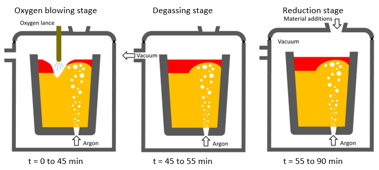

 تلاش میکنیم اینجا با مفاهیم و روشهای اصولی و حرفه ای بازرسی و تست و کنترل کیفیت آشنا شویم. مقالات و مطالب در دو سطح فارسی و انگلیسی ارائه می گردد. در صورت تمایل به درج مطالب در این وبلاگ لطفا با اینجانب تماس بگیرید تا مطالب شما بر اساس سیاست های وبلاگ درج گردد.